Contents of this article
In this article I describe Layer 2 switching basic concepts in networking for CCNA Exam. Switch forwards the data packets within the same local network. The data packets forwarded by switch on the basis of MAC table which is stored in its operating system. The basic functionality of switch is to forward the data packets to its destination by MAC filtering.
Layer 2 switch connects two or more different devices within a local area network. Switch works like a relay for data transfer between end devices. When the destination of a data packet is beyond the LAN, the packet forwarded to the gateway router. Layer 2 switching basic concepts is important part to learn for CCNA exam. In this article I describe the Layer 2 switching basic concepts with some other related terms like loop avoidance in a network.
Role of a Switch in a network
A Switch is a networking device which works at Data link layer in networking. A Switch receive and transmit the data packets between different end devices. We can say the Layer 2 switching basic concepts are related to receive and transmit the data packets in a network. Switch inspect the header section of the received packet to check the destination IP address and MAC address then forward accordingly. A switch can connect the computers via Ethernet port, Fast Ethernet port and optic fibre port. Switch works on its operating software which store the MAC address of devices connected with the various interfaces of switch.
The layer 2 switch are always placed behind the gateway device. Router is generally used as gateway device for all data packets of a network. Layer 2 switch works like a bridge between the multiple devices in a computer network. Switch are used to the basic data packet forwarding function to high end configuration switching. The latest switch are capable to create and works with VLAN in the network. The broadcast domain can break by creating the VLAN in switches. Each port of switch creates it’s own collision domain.
Layer 2 switching basic concepts
layer 2 switching done at data link layer in OSI reference model. Data link layer uses MAC address of devices for data transfer. Layer 2 switch break the collision domain. Each port of the layer 2 switch have its own collision domain. Instead of switch, HUB define all ports in a single collision domain. Hub works on physical layer. You should know about the layered approach in a network for data packet switching. You can read the full article related to OSI reference model here.
Layer 2 switching basic concepts : Working of layer 2 switching
Before layer 2 switch, Old bridges were used in networking. Later switch replace these bridges. The bridges maintains content addressable memory filter table. This table was used to transmit the data to correct receiver. Layer 2 switches maintain MAC address table for same purpose. Layer 2 switch provides a fast speed data transmission in a network because its each port breaks the large collision domain.
Each port have its own collision domain. Layer 2 switch forward frames from one device to another. A router decide to forward or drop the packet on the basis of PUD attached with packet. This PUD have the IP address of source and destination. Layer 2 switch forward the frame on the basis of MAC address header on the frame. Layer 2 switch add MAC address of connected devices to its database itself automatically.
Layer 2 switching basic concepts : Functions of Layer 2 switch
The main functions of layer 2 switching are address learning, frame forwarding and loop avoidance. These three functions provides a fast and reliable data transfer in a network. Here we discuss in brief about these functions of layer 2 switching.
Layer 2 switching basic concepts : Physical address learning
Physical address learning is the one of important task in Layer 2 switching basic concepts. Here physical address means MAC address. Each networking device and endpoint device have it’s own unique MAC address. Layer 2 switch maintain a MAC address table in its IOS operating system. This table contains the MAC address of all connected device with the switch. When a frame received at any port of switch then switch filter the MAC address from the frame. If filtered MAC address is not stored in its MAC database then switch save the MAC address. This process done with each frame received by the switch. When a switch is powered on, its MAC address database remains empty.
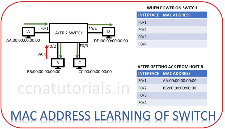
Now let’s device A want to transmit data for device B. Frame encapsulates device A at layer 2. Source address added to each frame transmitted via device A. Switch receive the frame at port F0/1.
As switch boot first time and have no MAC address database. Switch firstly save the MAC address of device A from frame header. Now switch transmit the same frame to each device connected with it except to device A. Device B forward an acknowledgement frame to switch that the frame destination is device B. On getting this acknowledgement switch store the MAC address of device B in its MAC address database table. Next time when device A or B send data to each other, switch forward the frame to correct address according to MAC address table. We can say now device A and B can communicate point to point with each other. Same process done till the MAC address of each connected device stored in its MAC address table.
Layer 2 switching basic concepts: Forward and Filter Decisions
Packet forward and filtering is related to Layer 2 switching basic concepts. We know how a layer 2 switch create and maintains it’s hardware address table. Forward and filter decisions at layer 2 switching depends on MAC database table. When a frame received at its interface. Switch look after the destination MAC address in frame’ header. On finding the destination hardware address it choose the interface to exit the frame. Each frame treat according to this process and forwarded to correct device.
On receiving a frame switch forward it to correct exit interface. The frame does’t sent to any other interface except it’s correct destination. This process is known as frame filtering. If the MAC address is not found in MAC database then switch flood the frame to each port except the interface of frame source.
Layer 2 switching basic concepts :Loop Avoidance function
When multiple switches are connected in different segments then chances of Loop occurs increased in a network. Loop avoidance is important for better performance of the network. Spanning Tree Protocol is used to prevent the network loops. In large networks redundant links used between switches to avoid communication failure. Redundant links meaning if a link failed due to any reason next link will active automatically. Chances of communication failure are less. Sometime the redundant links creates network loop. This is because frames can be transmitted to all redundant links and creating loops. As shown in figure below.
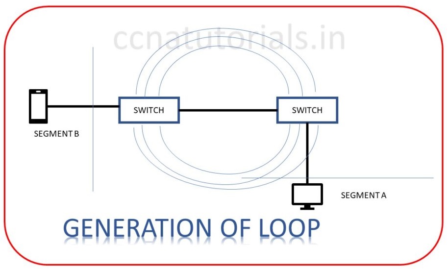
A host receive multiple copies of the same frame from different segments. Switch will not filter the frame because frame received from multiple interface on switch. Switch will save the MAC address of multiple frame and fail to forward the frame. This is known as thrashing the MAC table. This will creates a big flood of unnecessary data in the network.
Poor performance slow speed will occur. One remedy to avoid loop back is to reboot the switches of any one segment. But in a large network rebooting of switch is a big deal. To avoid these problems spanning tree protocol used. The above three functions are main part of Layer 2 switching basic concepts. Now lets see the function of loop avoidance in a network which is also related to Layer 2 switching basic concepts.
Loop avoidance in Layer 2 switching basic concepts
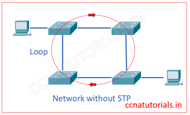
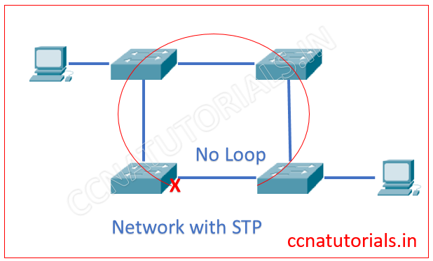
In this section I describe Spanning Tree protocol STP which is also related to Layer 2 switching basic concepts. Spanning Tree Protocol STP provide the loop avoidance in a network, where multiple switches are connected with each other as shown in below image. The Spanning Tree Protocol STP is layer 2 protocol.
STP automatically shut down the redundant links which creates the loops. The redundant link creates a loop between switches. STP monitors all links of the network. Spanning Tree Protocol STP finds the redundant link by the Spanning Tree Algorithm. The STA algorithm creates a topology database to find the redundant links.
Function of Spanning Tree Protocol STP : Layer 2 switching basic concepts
To explain the function of STP I select the network as shown in above image. There are four switch connected with each other. It is possible the loop may automatically create between switches. This loop is vulnerable to the network. You can assume the result of such loops.
We configured STP in a switch. The STP finds the redundant link which creates loop and disable it. After disabling a switchport the loop creation is stopped. The below image explain itself the STP.
Root Bridge and Bridge ID of STP for Layer 2 switching basic concepts
The Root Bridge is a switch which have lowest bridge priority ID. The Root Bridge switch is the main focus point for all switches in the network. Root Bridge is the main switch of the network. In case the bridge priority value is same in all network switches, the lowest MAC ID use to select the root bridge. In Cisco switches the default bridge ID remains 32768.
This Bridge Id can be manually changed. So if you want to make a particular switch root bridge, you need to change its bridge id. Every time when network topology changed the root bridge may be changed. I mean when a new switch added to network or any existing switch removed from the network. In case of failure of Root Bridge, remaining switches automatically select the next root bridge.
Non Root Bridges for Layer 2 switching basic concepts
All bridges except the root bridge are known as Non Root Bridge. Non Root Bridges communicate with root bridges and keep update the STP topology database.
BPDU in Layer 2 switching basic concepts
BPDU are multicast frame which transmitted between the switches. BPDU contains the information of all connections and link of a switch. BPDU also contains the Bridge ID of a Bridge.
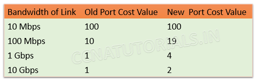
Port Cost in Layer 2 switching basic concepts
Port Cost is defined by the data transfer speed or bandwidth of a link. The Port cost is the main factor to determine the best path among the multiple links. Below image show the port cost of Cisco switches.
Path Cost in Layer 2 switching basic concepts
Path cost is dependent value of port cost. It is always counted from the root bridge. When BPDU broadcast from the root bridge the Path cost remains 0. Each switch received the BPDU add 1 to the path cost. So we can say if there are two switch in a path from Root Bridge to a switch the path cost will be 4 for that switch.
Root Port in Layer 2 switching basic concepts
The root port is the link with lowest path cost. In other words we can say the directly connected link with the root bridge is known as root port. In case more than one links connected with the root bridge bandwidth of each link define the lowest cost port and become the root port.
Designated Port in Layer 2 switching basic concepts
Designate port is the port which have lowest cost to the network segment compared to other ports on that network segment. Designated port also known as forwarding port. A network segment can have only one forwarding or designated port.
Non Designated port in Layer 2 switching basic concepts
All ports having higher cost than the designated port known as non-designated port. These are not forwarding ports.
Forwarding port in Layer 2 switching basic concepts
A root port or designated port forwards frames and known as forwarding ports.
Blocked Port in Layer 2 switching basic concepts
A blocked port prevents the loops by blocking the frame forwarding. A blocked port do not transmit any frame in the network.
Backup Port in Layer 2 switching basic concepts
Backup port is a port on same network segment as on designated port.
Disable state in Layer 2 switching basic concepts
In disable state the port do not forward or receive any frame. We can say the port remain in idle state or not operational.
Spanning Tree Protocol STP Blocking state
When you power on a switch, all ports remain in blocking state. A block port does not forward any frames in the network. A blocked port only listen to the BPDUs. Blocking state prevent the loops in the network.
Spanning Tree Protocol STP Listening state
In listening state the ports received the BPDUs. Listening ports make sure no loops occurs in the network. Listening ports forward the data frames without advertise the mac address table.
Learning state of STP in Layer 2 switching basic concepts
In learning state the ports still listen the BPDUs. Only root and designated ports go into the learning state. In learning state switch see the source address of frame and update the MAC table. Learning state time is 15 seconds only.
Spanning Tree Protocol STP Forwarding state
In forwarding state the port receive and forward the data frames. Switch forwarded the MAC address in forwarding state. This state take place after completion of convergence.
In this article I describe some terms related to Layer 2 switching basic concepts for CCNA exam. I hope you found this article helpful. For any query or suggestion you may drop a comment below or contact us. Your suggestions are always welcome by us.

hello, how can i solve this problem with this page showing? eye