In this article I explain the basics to configure and verify VLAN in cisco switch for CCNA exam 200-301. The basic concepts to configure and verify VLAN are very important part for CCNA 200-301 exam. This article consist the default VLANs in a switch, creation of new VLANs, Verify the VLANs and working with VLANs in a network.
We know that routers provides communication between different networks. It is known as internetworking. What if we have a LAN and wants to divide it into different LAN segment. Concept of VLAN raise from this question. If I have a small LAN which managed with some layer 3 switch, I want to divide this LAN into small LANs which do not interfere each other. The small LAN can only be created virtually otherwise we require a router to break the LAN into small LANs.
Here the basic concept of network and internetworking comes in picture. I mean Broadcast domain and Collision domain. We know that a Layer 3 switch breaks the collision domains and Router breaks the broadcast domains. Our requirement here is to break the LAN into broadcast domain. This requirement can be done by creating VLANs in a LAN by using Layer3 switch. To create VLAN in a LAN and communicate with each other is very easy now without Router.
Basic Requirements to Configure and Verify VLAN
All Cisco swith provides the connectivity to the devices within a VLAN. By default all switchports belongs to a single VLAN. It means all devices connected to the switch can communicate in a single broadcast domain. We can create new VLANs and bind the switchports to any VLAN as per our requirement. There is nothing require more than a layer3 switch to break the collision domains into broadcast domain.
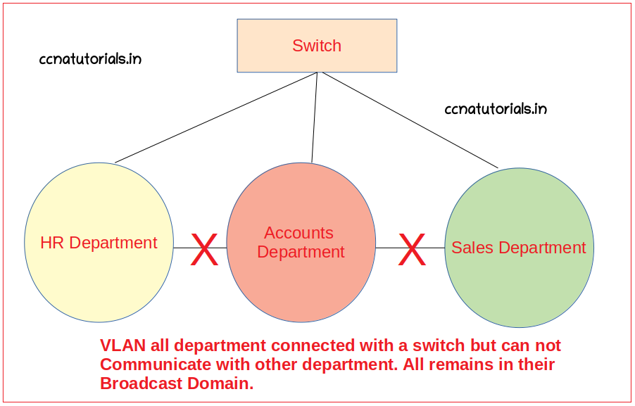
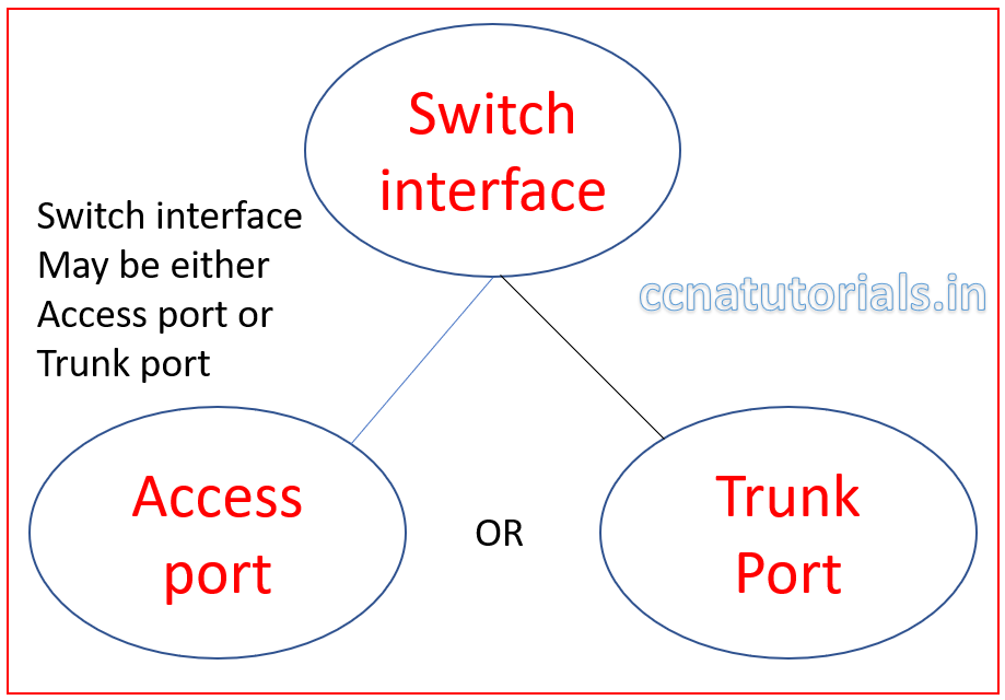
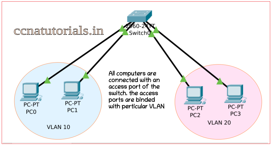
The different VLAN works on same subnet without disturbing other VLAN users. In the scenario shown in diagram below the LAN is divided into three segments. The user of particular segment can communicate with each other. Communication between different VLAN users is not possible after creation of VLAN in switch. The switch interfaces works in two modes one is access port and another is trunk port. Access port allow a device to send and receive data from the same VLAN only. Trunk port transmit the data of all VLANs from one switch to another switch.
You can do same thing with a Layer2 switch by assigned different subnet mask to computer. The main difference between subnetting and VLAN is that subnetting take place on Layer2. VLAN works on Layer 3. now one question comes in mind how to communicate particular two VLAN without interfere Third VLAN. The answer is inter-VLAN Routing with the help of Router. Later we do configure the inter-VLAN routing. In this article we discuss only the VLAN basic concept.
Requirement and necessity of VLAN
In a small office the computer can be connected with a Switch. We know there are multiple departments in a office like HR, Accounts, Sales and admin etc. A LAN works in a single broadcast domain. So when all computer works together there will network congestion occurs. The main problem is that the every computer can share the information to each computer. What will accounts do with the data of HR.
So the requirement is that each department computer should be work separately. There should be no information interchange between different departments. This requirement required a router because router breaks the broadcast domain. It is very expensive to install a router for each department.
So overcome these all problems the concept of VLAN takes place. VLAN can be created within a LAN. There is no requirement of router to separate the interfaces according to department. VLAN separate the computer connected with a switch. The computer of any department can communicate with each other without interfering other department’s computer. You can create 1 to 4094 VLAN in a LAN managed by cisco switches.
Structure of VLAN in a Cisco switch
All switch interfaces belongs to single VLAN 1 by default. You can say all interfaces of switch works in a single broadcast domain. We need to break that single broadcast domain virtually in many VLANS. We can bind the ports to a particular VLAN. For example port 1 to 4 belongs to HR department, port 5 to 8 belongs to accounts department etc.
It will break the single broadcast domain virtually not physically. Physically all ports works in a single switch. After configure the VLANs in a switch configure the same VLANs in other switch and connect them with the help of trunk port. You can increase the number of hosts in each department.
Frame Tagging in VLAN to Configure and verify VLAN
Frame tagging in VLAN is most important to distinguish the data of different VLANs. The main function of VLAN depends on the frame tagging which forward packets within a single VLAN. We know that the VLANs created in a LAN and our target is to Configure and verify VLANs in a LAN.
All computer and devices connected with a common switch can be breaks into multiple broadcast domains by creating VLANs. In a common LAN a data packet contains the source and destination mac address of device. It is not possible to identify a data packet of a particular VLAN with destination MAC address.
Frame tagging in VLAN provides the identification of data packets belongs to which VLAN. Frame tagging in VLAN helps to forward the data packet to its destination VLAN and device. When data packet required to send out of LAN IP address of destination network tagged on it by router. VLAN is independent of Router. Only a switch identifies the data packet and forward it to its destination VLAN.
Function of Frame Tagging to Configure and verify VLAN
Remember the concept of data packet flow in LAN and internetworks. Data packets contains the destination computer physical address when forwarded to a computer within LAN. Data packets tagged an IP address when forwarded out of LAN. Here the concept is simple, now you have VLAN in place of LAN. Switch maintains a table of physical address of connected device connected to interface.
We breaks the a big LAN into small VLANs. Now the LAN is not working for all devices connected to switch. Each VLAN function like a independent LAN. If you want to transfer a data packet to other VLAN, you need a router. Here the topic is about frame tagging in VLAN.
Data packets forwarded from switch to switch for same VLAN. To identify the data packets VLAN a frame tagged by the switch interface when data packet received on it. The frame tag on packet is the VLAN identity. This frame tag provides the identity of VLAN to which the packet belongs. So that the data packet can be sent to its destination within the same VLAN. The packet can be forwarded from one switch to another switch by trunked link.
Process of data flow with frame tagging in VLAN
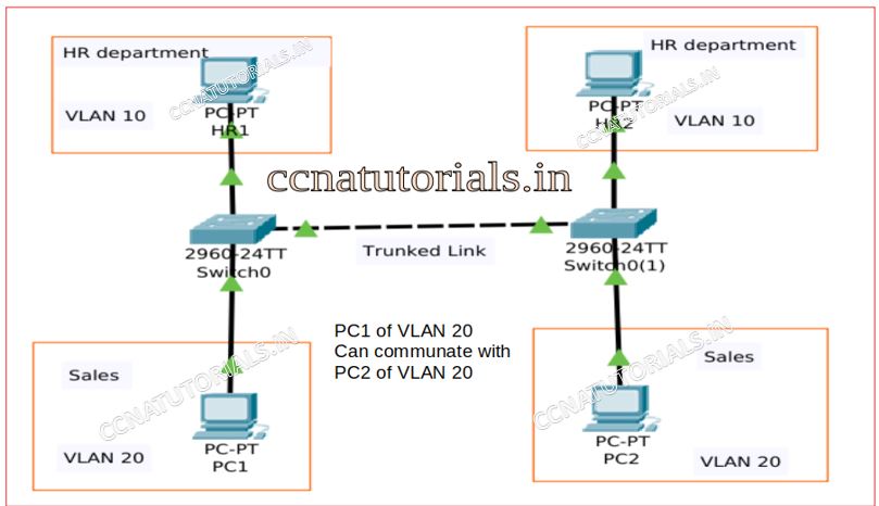
Assume there is a VLAN name Sales in a LAN. The VLAN is configure in both switches as shown in figure. Both switches connected with the trunked link. A computer PC1 want to communicate with PC2 in same VLAN but connected with another switch.
PC1 transmit a packet with the destination of PC2 to the switch1. On receiving the packet switch firstly tag a frame with the identity of VLAN sales. Switch1 search for MAC address in its local VLAN. As we can see the PC2 is connected with another switch2. Switch1 forward the packet with frame tag of VLAN identity to switch 2 via the trunked link.
On receiving the packet of trunk port switch 2 identify the frame tag on the packet. Switch identifies the VLAN identity firstly. The packet handed over to the VLAN whose identity is tagged on the packet. On receiving the packet by VLAN. VLAN check the MAC address tagged on the packet and the packet forwarded to PC2. No any other VLAN interfere in it and other VLANs don’t know what happens in VLAN sales. So this is the process of data flow with frame tagging in VLAN.
Access and Trunk Ports to Configure and Verify VLAN
Any swithport can work like an Access port or a trunk port during Configure and verify VLAN. Access and Trunk ports belongs to Layer 3 switch. Function of Access and Trunk ports are different. According to name of ports access ports provide facility to flow the data packets through it. Trunk ports allow to pass the traffic of multiple VLANs through it.
Access and Trunk ports play an important role for creating VLANs in a LAN. VLAN created on access ports in a layer 3 switch. Trunk ports provides connectivity between VLAN to VLAN from one switch to another switch. In this article we discuss only of basic of access and trunk ports. A switch-port can be assigned either access port of trunk port. It is not possible to assign both properties access and trunk ports to a single port.
Importance of Access ports to Configure and verify VLAN
Access port belongs to a particular VLAN. By default, all access ports of a switch remain in a VLAN 1. It means any device connected with any access port can communicate with another device. The condition is that all devices should have a same subnet mask. If all devices have same subnet mask, it means all devices belongs to same network ID can communicate with each other. Access ports receive and transmit the data for the same VLAN.
The access port doesn’t check for source address on data packets. VLAN works as a separate broadcast domain in a LAN. You can say if there are 5 VLANs in a LAN, there are 5 broadcast domains lying in the LAN. Each device belongs to VLAN assume in separate broadcast domain. The access ports in a VLAN works like separate collision domain for the connected device. Devices of different VLAN can communicate by configuring inter-VLAN routing with the help of a router. The router works like a gateway between the VLANs.
One access port can be assigned to a single VLAN only. It is not possible to assign two VLANs to a single access port. For data transfer only single VLAN can be accessed by an access port. When you are working with voice and data transfer via a single access port. You can assign a data VLAN and a voice VLAN to a single access port. But the rule is that only single VLAN of same pattern can be assigned to an access port.
Importance of Trunk Ports to Configure and verify VLAN
Trunk ports are not separate ports on a layer 3 switch. Any interface can be defined as Access or Trunk port. The task of trunk port is to carry the data of all VLANs available in the whole switch interfaces. I mean to say suppose you have 4 VLANs in a switch and want to carry all 4 VLANs data to another switch via a single port. In this case you must assign a single port as trunk port in that switch. Similarly, in another switch a single port also assigned trunk port.
Both switches should be connected with the trunk port to make communication between all VLANs of different switches. A trunk port can carry the data of all VLANs together for another trunk port. We can say just like a telephone line which can carry multiple voice calls without disturbing each other. The trunk port can carry multiple VLANs data without interfering each other in a network. A trunk link speed is 100, 1000 or 10000 Mbps point to point link between two switches.
Access and trunk ports explained to Configure and verify VLAN
See the below diagram. Here I have taken three VLANs with same configuration with two different switches. The name of VLANs are HR, Acctt and Admin. The devices belong to HR can not communicate with other VLAN. In a single switch it is possible and feel good. The access ports of each VLAN are assigned the concern VLAN name.
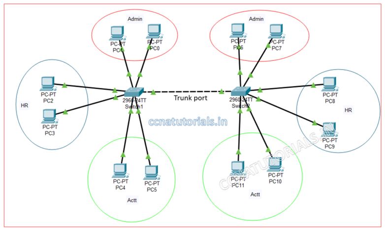
Now my requirement is to establish another office in the same block with different switch. How to manage same thing in another switch and the client of HR switch 1 should be communicate with HR switch 2. Similarly, the user of Admin branch switch 1 should be communicate with Admin branch switch 2.
This requirement can be done by creating an interface to trunk port in both switches and connect them with each other. One thing to remember that the VLAN configuration in both switches should be same. All devices belong to particular VLAN should be connected with same VLAN in another switch and the network ID should be same for all devices in same VLAN.
Configuration of access port and trunk port in a switch
A switch port can configure access and trunk mode by some simple commands. Remember the basic functionality of access and trunk mode of a switch port. Access mode port can receive the data of same VLAN tag and transmit the data within the same VLAN. Trunk mode port connects different switch.
A trunk mode port can carry the data of multiple VLAN through it. At the end the trunk mode port distribute the data packets to related VLAN ID. Access mode port works like a single line phone. Trunk mode port works like a carrier for multiple telephone lines. The identification method in access and trunk mode port is frame tagging on packet with VLAN Id.
Configure access mode to a port of switch
All switch ports remains in single VLAN 1 and in access mode.by default. Once you change the switch port to trunk mode the default property of switch port vanish. To get back a switch port from trunk mode to access mode you need to run the below command from global command mode of CLI. Suppose we need to change the mode of FastEthernet 0/1 to access mode.
Switch>en
Switch#config t
Enter configuration commands, one per line. End with CNTL/Z.
Switch(config)#interface fastethernet 0/1
Switch(config-if)#switchport mode access
Switch(config-if)#exit
Switch(config)#do wr
Building configuration...
[OK]
Switch(config)#
Switch#
Similarly we can change the mode of any switch port. It is not necessary the switch port must be fastethernet port. Any interface port of switch can be changed to access mode. It may be GigabitEthernet also.
Configure Trunk mode to a port of switch
We know by default all ports of a switch remain in access mode. We want to send the data from one VLAN to same VLAN on other switch than we need to configure a switch port to trunk mode. Trunk mode port can receive and transmit the data of multiple VLANs via a single media.
The trunk port may be any FastEthernet port of GigabitEthernet port. The commands are same as we discuss above. Here I am going to change the mode of switchport GigabitEthernet 0/1 port to trunk mode. Remember one thing once you changed the mode of any switch port do not connect any VLAN device with it. The trunk mode port does not belong to any VLAN. It carry the data of all VLANs together. So see the below commands to change the mode of GigabitEthernet port 0/1.
Switch>en
Switch#config t
Enter configuration commands, one per line. End with CNTL/Z.
Switch(config)#interface GigabitEthernet 0/1
Switch(config-if)#switchport mode trunk
Switch(config-if)#exit
Switch(config)#do wr
Building configuration...
[OK]
Switch(config)#
Switch#
Now the GigabitEthernet 0/1 port will behave like a tunnel for all VLANs to carry the data from one switch to another connected switch via trunk ports. You can set the speed of link and duplex mode for the trunk switch port.
Checking the mode of a switchport
You can check the mode of a particular switch port or all ports at once. By running the “show interfaces” you can see the status of all interfaces. But i need to check only trunk ports of the switch then i will run the following command.
Switch#show interfaces trunk
Port    Mode        Encapsulation   Status    Native vlan
Fa0/1    on         802.1q          trunking    1
Port Vlans allowed on trunk
Fa0/1 1-1005
Port Vlans allowed and active in management domain
Fa0/1 1
Port Vlans in spanning tree forwarding state and not pruned
Fa0/1 1
In above command window you can see the first result of command “show interfaces trunk”. The status of Fa0/1 is trunk. If you have multiple trunk ports than this command will show all trunk ports status.
Configure and verify VLAN in Cisco Switch
We can configure and verify VLAN in Cisco Switch by some simple commands in CLI. A switch can hold VLAN from 1 to 4094. All interfaces of a switch remain in a single VLAN 1 by default. There are two tasks to configure VLAN in Cisco switch. Firstly, we assigned the VLAN in the switch. After assigning the VLAN number we bind the interfaces with VLAN. All devices connected with switch from one VLAN can communicate within VLAN. It is not possible for any device to communicate with other VLAN’s device. To enable the communication between different VLAN’s devices we need a router.
Function of VLAN in Cisco switch.
The switch ports may be access port of trunk port. It is not possible that a port assigned both access and trunk properties. The function of access mode is simple. Access port received the data packets from the same VLAN from where the data packet transmitted. Access ports allow only single VLAN data transfer through it.
Trunk port can carry data packets of multiple VLAN at a time. VLAN makes the separate broadcast domain for each VLAN. The devices belong to a VLAN can communicate within the same broadcast domain or same VLAN. The network ID of different VLAN may be different or same. Network ID do not play any role in data transfer within a VLAN. Switchport interface assigned to particular VLAN. IP address of devices doesn’t matter for data transfer in VLAN.
Configure and verify VLAN step by step in a cisco switch
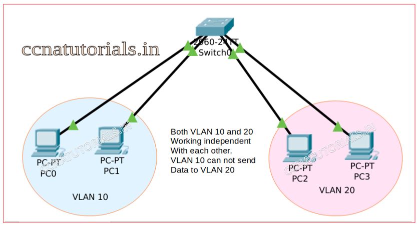
We configure three VLAN in a cisco switch. Four interfaces assigned to each VLAN. I mean switchport 1-4 for VLAN 10, 5-8 for VLAN 20 and 9 -12 for VLAN 30. Port 24 mode set to trunk port. By default, all switchports remains in access mode. We do not need to change the mode of any switchport.
Mode of switchport require to change when we need a trunk port. We can change the mode of any switchport from access to trunk and vice versa. To configure VLAN in cisco switch firstly we define the VLANs after that we assigned the interfaces to each VLAN and try to ping the computer connected with different VLAN.
I keep the same network ID for all devices of all VLANs. See whether the devices of different VLAN communicate with each other or not. We know the devices with same network ID in a network communicate with each other. See whether VLAN breaks the broadcast domain for different VLAN.
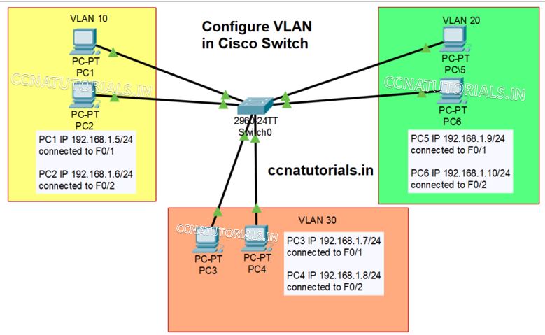
Design a small network like shown in picture shown above. Assign IP address of network ID 192.168.1.0/24 to all PC connected with the switch. Connect PC1 and 2 on switchport Fast Ethernet 0 and 1.
Similarly connect PC3 and 4 with Fast Ethernet 5 and 6 and PC 5 and 6 with Fast Ethernet 9 and 10. We set the VLAN 10, 20 and 30 in switch. Now try to ping all PC with each other. You can all PC can ping each other. Now we configure the different PCs to different VLANs.
Commands to configure and verify VLAN in cisco switch
Follow the commands shown in below command window to create VLAN 10, 20 and 30.
Switch>enable
Switch#
Switch#vlan database
Switch(vlan)#vlan 10
VLAN 10 added:
Name: VLAN0010
Switch(vlan)#vlan 20
VLAN 20 added:
Name: VLAN0020
Switch(vlan)#vlan 30
VLAN 30 added:
Name: VLAN0030
Switch(vlan)#exit
APPLY completed.
Exiting....
Switch#wr
Building configuration...
[OK]
Switch#
Three new VLAN created by running above commands. You can verify the created VLAN by running “show vlan” command in command line interface. See the example below.
VLAN Name Status Ports
---- -------------------------------- --------- -------------------------------
1 default active Fa0/1, Fa0/2, Fa0/3, Fa0/4
Fa0/5, Fa0/6, Fa0/7, Fa0/8
Fa0/9, Fa0/10, Fa0/11, Fa0/12
Fa0/13, Fa0/14, Fa0/15, Fa0/16
Fa0/17, Fa0/18, Fa0/19, Fa0/20
Fa0/21, Fa0/22, Fa0/23, Fa0/24
Gig0/1, Gig0/2
10 VLAN0010 active
20 VLAN0020 active
30 VLAN0030 active
1002 fddi-default active
1003 token-ring-default active
1004 fddinet-default active
1005 trnet-default active
VLAN Type SAID MTU Parent RingNo BridgeNo Stp BrdgMode Trans1 Trans2
---- ----- ---------- ----- ------ ------ -------- ---- -------- ------ ------
1 enet 100001 1500 - - - - - 0 0
10 enet 100010 1500 - - - - - 0 0
20 enet 100020 1500 - - - - - 0 0
30 enet 100030 1500 - - - - - 0 0
1002 fddi 101002 1500 - - - - - 0 0
1003 tr 101003 1500 - - - - - 0 0
1004 fdnet 101004 1500 - - - ieee - 0 0
1005 trnet 101005 1500 - - - ibm - 0 0
VLAN Type SAID MTU Parent RingNo BridgeNo Stp BrdgMode Trans1 Trans2
---- ----- ---------- ----- ------ ------ -------- ---- -------- ------ ------
Remote SPAN VLANs
------------------------------------------------------------------------------
Primary Secondary Type Ports
------- --------- ----------------- ------------------------------------------
Switch#
Assigning ports to VLAN as a part of configure and verify VLAN
We have created three VLANs in cisco switch. As shown in above command line all interfaces of switch belong to VLAN1. We must assign the switchports belongs to related VLAN. Assign switchport 1 to 4 to VLAN 10, 5 to 8 to VLAN20 and 9 to 12 to VLAN 30.
Assign FastEthernet ports to relate VLANs
We need to assign the switchports to related VLAN one by one. We need to run following commands in CLI to assign the switchports to VLAN. I am showing only two switchports for example. You must assign all switchports to different VLAN. To assign switchport F0/1 and F0/2 to VLAN 10 run the following commands.
Switch>
Switch>enable
Switch#
Switch#configure terminal
Enter configuration commands, one per line. End with CNTL/Z.
Switch(config)#interface FastEthernet0/1
Switch(config-if)#switchport access vlan 10
Switch(config-if)#exit
Switch(config)#interface fastethernet0/2
Switch(config-if)#switchport access vlan 10
Switch(config-if)#exit
Switch(config)#exit
Switch#
%SYS-5-CONFIG_I: Configured from console by console

Switch#wr
Building configuration...
[OK]
Switch#


Similarly assign the remaining switchports to VLAN 20 and 30.


Switch>
Switch>enable
Switch#
Switch#configure terminal
Enter configuration commands, one per line. End with CNTL/Z.
Switch(config)#interface FastEthernet0/5
Switch(config-if)#switchport access vlan 20
Switch(config-if)#exit
Switch(config)#interface fastethernet0/6
Switch(config-if)#switchport access vlan 20
Switch(config-if)#exit
Switch(config)#exit
Switch(config)#interface FastEthernet0/9
Switch(config-if)#switchport access vlan 30
Switch(config-if)#exit
Switch(config)#interface fastethernet0/10
Switch(config-if)#switchport access vlan 30
Switch(config-if)#exit
Switch(config)#exit
Switch#
%SYS-5-CONFIG_I: Configured from console by console

Switch#wr
Building configuration...
[OK]
Switch#
After configure and verify VLAN in above small network. Try to ping the PC of VLAN 10 with PC of VLAN 20. You can see they are not communicating with each other. Only within VLAN PC can communicate with each other.
In this article I describe the basic concepts to configure and vefify VLAN in a small network. I hope you found this article useful. For any query or suggestion on the subject you may drop a comment below or contact us. Your suggestions are always welcome.
Like!! I blog quite often and I genuinely thank you for your information. The article has truly peaked my interest.