In this article I describe the method to configure and verify interswitch connectivity in a network. A new switch can be added in network and it will work automatically on by default configuration. If you have some specific configuration like VLAN and VTP in your network then you need to configure and verify interswitch connectivity. Command line provides some commands of IOS to configure and verify interswitch connectivity. I describe some common related terms and commands required to configure and verify interswitch connectivity.
Function of a switch in a network
Layer 2 switch provides connectivity between two or more different devices within a local area network. Switch allow data transfer between end devices in a network. When the data packet is for out of LAN, the packet sent to the gateway router. A Switch is a networking device which works at Data link layer in networking. A Switch receive and transmit the data packets between different end devices. We required to configure and verify interswitch connectivity for data transfer between different devices. Switch inspect the header section of the received packet to check the destination IP address and MAC address then forward the packet accordingly. A switch can connect the computers via Ethernet port, Fast Ethernet port and optic fibre port. Switch works on its operating software which store the MAC address of devices connected with the various interfaces of switch.
The layer 2 switch are always placed behind the gateway device. Router is generally used as gateway device for all data packets of a network. Layer 2 switch works like a bridge between the multiple devices in a computer network. Switch are used to the basic data packet forwarding function to high end configuration switching. The latest switch are capable to create and works with VLAN in the network. The broadcast domain can break by creating the VLAN in switches. Each port of switch creates it’s own collision domain.
Function of Access and Trunk port to configure and verify interswitch connectivity
By default all switchports remain in access port mode. Access ports provide data transfer to connected devices within the network. The devices belongs to the access ports remains in same broadcast domain. The connected device can access receive and transmit the data only by using the access ports.
Trunk port mode allow to transmit and receive the data of multiple VLANs between different switches. The endpoint devices never connected with trunk ports of a switch. The switches use the trunk ports to connect with each other. For example when we need to connect two switches which have multiple VLANs, the switches can be connected via trunk ports. The assignment of access ports and trunk ports are logical. A switchport mode can be changed by using the command line interface.
IEEE 802.1Q frame tagging and native LAN in switch
The 802.1Q generally written as dot1Q is a data encapsulation method for VLAN tagging. Dot1q is Cisco proprietary and is also an open source protocol to use in VLANs. The length of VLAN tag is 4 bytes or 32 bits in length. Native LAN used for the data which have untagged Ethernet frames on trunk port. For Native VLAN both sides of the trunk line should have same configuration.
Process to configure and verify interswitch connectivity
I assume you know about the configuration of VLANs in a switch. See the image below this paragraph. I give the process with commands and examples to configure and verify interswitch connectivity between two switches. It will remind you some important commands of the IOS of a switch. I take two switches and configure same two VLANs in both switches. The name of VLANs are HR and Accounts. I configure first 4 ports for VLAN HR and next 4 ports for VLAN Accounts.
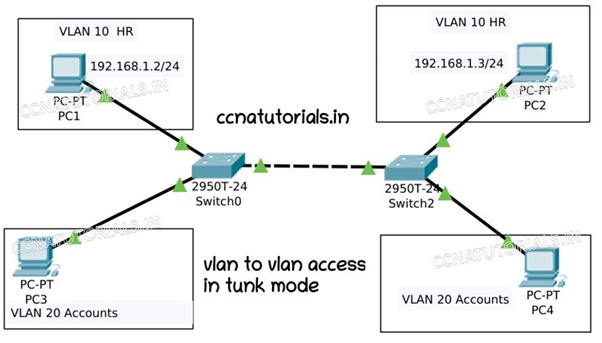
In both switches PORT number 24 reserve as trunk port. Port 24 will transmit and receive the data of all VLANs simultaneously. We connect both switch with port 24 for trunk mode transportation. So before going to VLAN to VLAN Access in Trunk Mode we need the following configuration.
You have to do the configuration of VLANs in both switches. I give an example for only one switch. See the below commands for configuration of VLANs in switch.
 Switch>enable
 Switch#config t
 Enter configuration commands, one per line. End with CNTL/Z.
 Switch(config)#vlan 10
 Switch(config-vlan)#name HR
 Switch(config-vlan)#exit
 Switch(config)#vlan 20
 Switch(config-vlan)#name Accounts
 Switch(config-vlan)#exit
 Switch(config)#do wr
 Building configuration...
 [OK]


 Switch#show vlan
 VLAN Name Status Ports
 ---- -------------------------------- --------- -------------------------------
 1 default active Fa0/1, Fa0/2, Fa0/3, Fa0/4
 Fa0/5, Fa0/6, Fa0/7, Fa0/8
 Fa0/9, Fa0/10, Fa0/11, Fa0/12
 Fa0/13, Fa0/14, Fa0/15, Fa0/16
 Fa0/17, Fa0/18, Fa0/19, Fa0/20
 Fa0/21, Fa0/22, Fa0/23, Fa0/24
 Gig0/1, Gig0/2
 10 HR active
 20 Accounts active
 1002 fddi-default active
 1003 token-ring-default active
 1004 fddinet-default active
 1005 trnet-default active
See the below commands to assign the switchports to VLANs and make port 24 as trunk port.
Switch>enable
Switch#config t
Switch(config)#interface FastEthernet0/1
Switch(config-if)#switchport access vlan 10
Switch(config-if)#exit
Switch(config)#interface fastEthernet 0/2
Switch(config-if)#switchport access vlan 10
Switch(config-if)#exit
Switch(config)#interface fastEthernet 0/5
Switch(config-if)#switchport access vlan 20
Switch(config-if)#exit
Switch(config)#interface fastEthernet 0/6
Switch(config-if)#switchport access vlan 20
Switch(config-if)#exit
Switch(config)#interface fastEthernet 0/24
Switch(config-if)#switchport mode trunk
 Switch(config-if)#exit
Switch(config)#do wr
Building configuration...
[OK]
Switch(config)#exit
Switch#
Assigning IP address to clients of VLAN HR.
We know that the configuration of VLAN is same in both switches. The network ID of clients in same VLAN should be same. For example i take the network ID for VLAN HR 192.168.1.0/24. According to this condition i assigned the IP address to the clients of VLAN HR as shown in figure. You have to assign the IP address manually for both PC1 and PC2. In this article I assigned IP address 192.168.1.2/24 to PC1 and 192.168.1.3/24 to PC2. After assigning IP address try to ping the PC1 with PC2. You will got the result as shown in command window below.
C:\>ping 192.168.1.3
Pinging 192.168.1.3 with 32 bytes of data:
Reply from 192.168.1.3: bytes=32 time=1ms TTL=128
Reply from 192.168.1.3: bytes=32 time=2ms TTL=128
Reply from 192.168.1.3: bytes=32 time<1ms TTL=128
Reply from 192.168.1.3: bytes=32 time<1ms TTL=128
Ping statistics for 192.168.1.3:
Packets: Sent = 4, Received = 4, Lost = 0 (0% loss),
Approximate round trip times in milli-seconds:
Minimum = 0ms, Maximum = 2ms, Average = 0ms
C:\>
Similarly you can try to make communication between other VLANs. Do it yourself you will found it useful. I hope you enjoyed and understood this article related to configure and verify interswitch connectivity. For any query or suggestion on this article you may contact us or drop a comment below. Your suggestions are always welcome by us.


It is not my first time to visit this website, i am visiting this site dailly and get pleasant information from
here all the time.
My homepage :: buy cbd gummies
Mare lichidare de stoc la Sereni Capelli pentru Tratament Impotriva Parului Alb / Carunt / grizonant!
Produsele functioneaza atat pentru Femei, cat si pentru Barbati, indiferent de varsta.
Nu pierde reducerile de azi pe serenicapelli.ro
Stocurile cu reduceri sunt limitate.
Big Clearance Sale at Sereni Capelli for Anti-Gray Hair Treatments!
The products work for both Women and Men, regardless of age.
Don’t miss today’s discounts on serenicapelli.com
Discounted stocks are limited.
I store #USDT in my OKX wallet and have my seed phrase (clean party soccer advance audit clean evil finish tonight involve whip action). Could you please tell me how to transfer this money to Binance?
Hello,
We are currently seeking companies like yours for a potential long-term partnership. Could you kindly share your product offerings along with pricing details? Please contact me on WhatsApp:+44 788 720 6429