In this article I describe the Basic concepts of Ethernet in computer networking. Basic concepts of Ethernet are necessary to understand any networking theory and practical part.
Ethernet works on Data link and physical layer of OSI reference model. Basic concepts of Ethernet is to access media or network from a device. The Ethernet provides connectivity between devices and network. Ethernet connector also known as RJ45 connector. Implementation and maintains of Ethernet is very easy. Ethernet port provides speed up to gigabits per second. Ethernet is responsible for formatting and transmission of data in a predefined format. Similarly, at the receiver end the received data reformatted in a predefined format.
Working of Ethernet : Basic concepts of Ethernet
Ethernet belongs to IEEE standard IEEE 802.3 family. Basic concepts of Ethernet working, Ethernet working depends on both physical and data link layer. The Ethernet send and receive the bits and frame in a network. Physical layer defines the bits streaming and data link layer defines the frame streaming. Ethernet is responsible for VLAN tagging, QOS, error correction and identify the transmission problems.
Collision Domain and Broadcast Domain depends on Ethernet protocols. Collision and broadcast domain define by layers protocols. Ethernet connectors and ports are used to connect the hub, switch, router with each other.
Collision Domain: Basic concepts of Ethernet
Collision Domain term related to hub or physical layer devices. Hub use a common media to send and receive the data. Hub works as a shared media in an Ethernet network. Data flow on a single media and collapse several times. This is the reason of collision and the devices belongs to this network are lie in a common collision domain. Bus topology is the best example of collision data. Bus topology and Ethernet hub are half duplex. These devices can send or receive data at the same time.
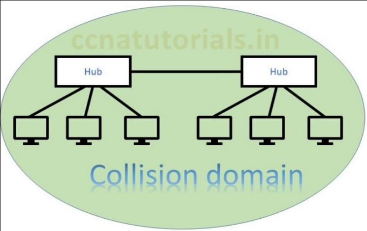
In above picture two hubs are connected with each other. Both hubs are in a common collision domain. Hub works on physical layer transmit the data to all connected devices. This is why collision occurs. In this scenario data lost generally and the sender must resend the data. Data collision responsible for poor network performance. In Basic concepts of Ethernet collision domain and broadcast domain are two factors used in connectivity.
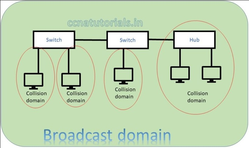
In above picture two switch creates a network. Both switch and connected device are in a single broadcast domain. Each port of switch itself creates a separate collision domain. There are four collision domains. All devices connected with a Hub remains in a collision domain.
According to both above pictures we can say a switch breaks collision domain. Switch can not break a broadcast domain, so all ports of a switch belongs to a broadcast domain. Creation of VLAN in switches breaks the broadcast domain. By using switch in place of hub the collision domains break and performance of network improved.
In above example you learn about collision domain. How collision domain occurs and how to overcome the collision of data in a network.
Broadcast Domain in Basic Concept of Ethernet
Broadcast domain defines the boundary of data broadcasting. All ports of a switch belong to a single common broadcast domain. Each port of a switch breaks the collision domain and create its own collision domain. Each port of a router breaks the broadcast domain. The port of a router have its own broadcast domain. Further switch uses to break the collision domain. In a broadcast domain device communicate via Data Link Layer.
The below picture shows the difference of broadcast and collision domain. Switch breaks collision domain and router breaks the broadcast domain.
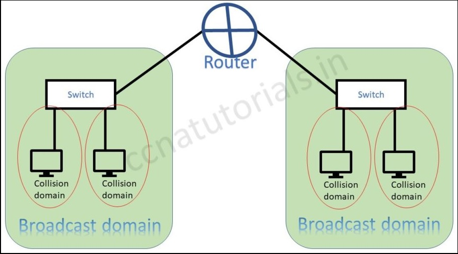
Switch can break the broadcast domain logically via creating VLAN. A router creates broadcast domain boundaries. The size of broadcast domain is responsible for performance of network. It is good to keep the broadcast and collision domain as small as possible. This practice will improve the network performance also data flow speed. I hope in Basic Concept of Ethernet relation of broadcast and collision domain is clear now.
CSMA/CD in Basic Concept of Ethernet
CSMA/CD acronym for Carrier Sense Multiple Access with Collision Detection. The CSMA/CD protocol overcome the collision problem occurs in a network segment. Which helps devices share the bandwidth in a network segment. CSMA/CD control the data flow in a network segment. This protocol prevents multiple devices to transmit data simultaneously. This prevention improves the network performance.
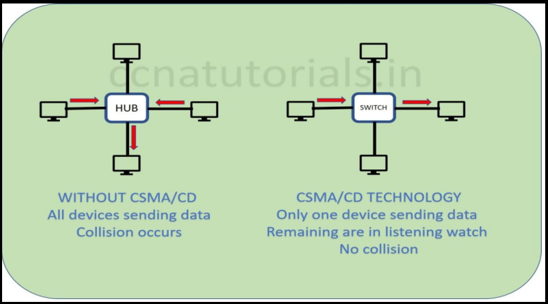
In below picture CSMA/CD protocol working defines. The hub network shows all devices transmitting data simultaneously. This will make poor network performance and data collision occurs. In switch network diagram only one device transmitting the data. Remaining all devices are receiving and waiting for their turn to transmit.
Working of CSMA/CD protocol
In above diagram see the switch network. Suppose a computer need to transmit data for another one. Sender computer sense the signal in the transmission media. In case there is any signal found transmitting then sending computer will wait to finish it. This protocol works for all devices. So, it become easy to control the traffic in a network.
Half- and Full-Duplex Ethernet
IEEE 802.3 standard identify the half duplex ethernet. In half duplex ethernet the data flow one side at a time. Suppose two devices are connected with half duplex ethernet. At one time only one device can send the data. Half duplex ethernet uses the CSMA/CD protocol. Collision occurs in Half duplex ethernet network. A hub relates to a switch works like a half-duplex ethernet network. Data flow speed is very low in a half-duplex network due to collision.
Half-duplex ethernet network uses one pair wire for flow of data in the network. Full-duple ethernet works on two pair wire. Full-duplex ethernet uses point to point connections between sending and receiving device. Full duplex ethernet network works like a telephone communication. Simultaneously data send and receive in a full-duplex network. Data flow speed is fast in a full-duplex ethernet network than half-duplex ethernet network. Each device has its own collision domain in full-duplex ethernet network. CSMA/CD protocols are used in full-duplex ethernet network.
Ethernet Addressing
Ethernet addressing is identification of Hardware. A unique MAC address is assigned to each network interface card. NIC may be physical media or wireless media. MAC address is acronym for Media Access Control. IEEE standard gives a format of MAC address as shown in figure below. This format should be followed by every hardware maker. By following the format any manufacturer NIC can communicate with each other.
MAC address is a combination of six bytes in hexadecimal format. MAC address written once on NIC cards when it manufactured. 48 bits divided in six octet section. 24 bits assigned for organisationally unique identifier (OUI). OUI assigned by the IEEE to an organization.
Ethernet Frames
Bits combining to bytes and bytes to frames at data link layer. Frames encapsulates packets at data link layer. Ethernet stations pass the data frames in the form of MAC frame format. This provides error detection from a cyclic redundancy check (CRC). This is error detection only, not an error correction.
Ethernet Port security
Without binding ports of a switch any device can join to the switch. This is not a good thing and a security breach of the network. Port security of layer 2 switching is necessary to avoid such things. We know each device have its own unique hardware address called MAC address. This MAC address is used to bind a port with a particular device.
Remember Wi-Fi, How we connect a device to wireless network. There are many security method to keep secure the wireless network. There are some security feature available in layer 2 switches. One of these feature is port binding with MAC address. Without port security anyone can add a device in network. Also there are chances of adding hub or switch with a unsecured port.
I hope you found this article helpful to understand the Basic Concept of Ethernet. For any suggestion or query you may drop a comment below or contact us. your suggestions always welcome by us.