In this article I describe the Ethernet IEEE standard in Networking for CCNA Exam. Ethernet IEEE standard in networking is main part of learning the networking. Ethernet provides connectivity to the networking devices in a network. An Ethernet provides physical connectivity for data transfer in a network. There are various standards of Ethernet available according to the speed and reliability. IEEE institute defines some fix standards for Ethernet in networking.
Ethernet works on Data link and physical layer of OSI reference model. Ethernet IEEE standard in networking is related to access the media from a device. The Ethernet provides connectivity between nodes and different networking devices. Ethernet connector also known as RJ45 connector. Implementation and maintains of Ethernet is very easy. Ethernet port provides speed up to gigabits per second. Ethernet is responsible for formatting and transmission of data in a predefined format. Similarly, at the receiver end the received data reformatted in a predefined format.
Working of Ethernet: Ethernet IEEE standard in Networking
Ethernet belongs to IEEE standard IEEE 802.3 family. Ethernet IEEE standard in working, Ethernet working depends on both physical and data link layer. The Ethernet send and receive the bits and frame in a network. Physical layer defines the bits streaming and data link layer defines the frame streaming. Ethernet is responsible for VLAN tagging, QOS, error correction and identify the transmission problems. An Ethernet do work metallic conductor cables. Ethernet cable may be co-axial, twisted pair or CAT-6 cables.
Collision Domain and Broadcast Domain depends on Ethernet protocols. Collision and broadcast domain define by the connectivity media like hub, switch etc. The Collision and Broadcast domain defined at different layers of OSI model. Before going to IEEE standards lets remember the Collision and Broadcast domain concetps related to Ethernet.
Collision Domain for Ethernet basic concept in networking
Collision domain term related to hub or physical layer devices. Hub use a common media to send and receive the data. Hub works as a shared media in an Ethernet network. Data flow on a single media and collapse several times. This is the reason of collision and the devices belongs to this network are lie in a common collision domain. Bus topology is the best example of collision data. Bus topology and Ethernet hub are half duplex. These devices can send or receive data at the same time. To overcome collision in a network CSMA/CD technique used. Later we will discuss about these Ethernet basic concept in networking.
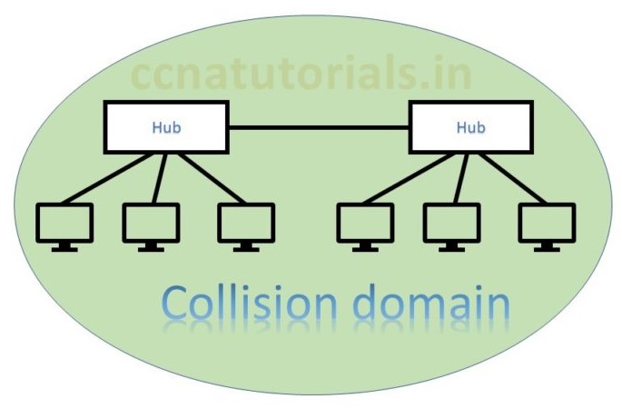
In above picture two hubs are connected with each other. Both hubs are in a common collision domain. Hub works on physical layer transmit the data to all connected devices. This is why collision occurs. In this scenario data lost generally and the sender must resend the data. Data collision responsible for poor network performance. In Ethernet basic concepts collision domain and broadcast domain are basic terms to know.
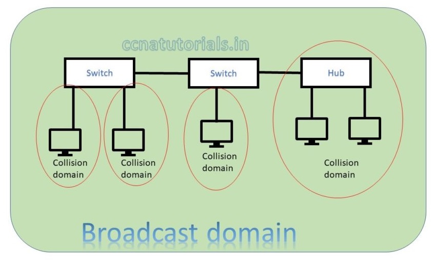
In above picture two switch creates a network. Both switch and connected device are in a single broadcast domain. Each port of switch itself creates a separate collision domain. There are four collision domains. All devices connected with a Hub remains in a collision domain.
According to both above pictures we can say a switch breaks collision domain. Switch do not break a broadcast domain, so all ports of a switch belongs to a broadcast domain. By using switch in place of hub the collision domains break and performance of network improved.
In above example you learn about collision domain. How collision domain occurs and how to overcome the collision of data in a network.
Broadcast Domain for Ethernet basic concept in networking
Broadcast domain defines the boundary of data broadcasting in a network. All ports of a switch belong to a single broadcast domain. Each port of a switch breaks the collision domain and create its own collision domain. Each port of a router breaks the broadcast domain. The port of a router have its own broadcast domain. Further switch uses to break the collision domain. In a broadcast domain device communicate via Data Link Layer.
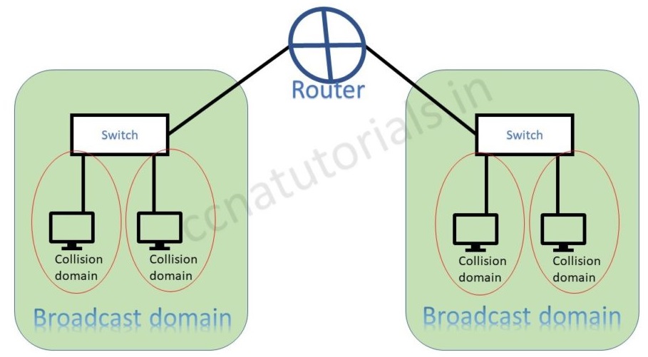
The above picture shows the difference of broadcast and collision domain. Switch breaks collision domain and router breaks the broadcast domain in a network.
Switch can break the broadcast domain logically via creating VLAN. A router creates broadcast domain boundaries. The size of broadcast domain is responsible for performance of network. It is good to keep the broadcast and collision domain as small as possible. This practice will improve the network performance also data flow speed. I hope in Ethernet basic concepts relation of broadcast and collision domain is clear now.
CSMA/CD for Ethernet basic concept in networking
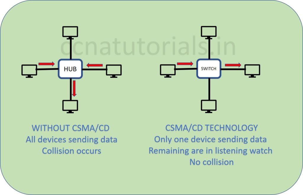
CSMA/CD acronym for Carrier Sense Multiple Access with Collision Detection. The CSMA/CD protocol overcome the collision problem occurs in a network segment. Which helps devices share the bandwidth in a network segment. CSMA/CD control the data flow in a network segment. This protocol prevents multiple devices to transmit data simultaneously. This prevention improves the network performance.
In below picture CSMA/CD protocol working defines. The hub network shows all devices transmitting data simultaneously. This will make poor network performance and data collision occurs. In switch network diagram only one device transmitting the data. Remaining all devices are receiving and waiting for their turn to transmit.
Working of CSMA/CD protocol for Ethernet Basic concept in networking
In above diagram see the switch network. Suppose a computer need to transmit data for another one. Sender computer sense the signal in the transmission media. In case there is any signal found transmitting then sending computer will wait to finish it. This protocol works for all devices. So, it become easy to control the traffic in a network.
Half- and Full-Duplex Ethernet IEEE standard in networking
IEEE 802.3 standard identify the half duplex Ethernet. In half duplex Ethernet the data flow one side at a time. Suppose two devices are connected with half duplex Ethernet. At one time only one device can send the data. Half duplex Ethernet uses the CSMA/CD protocol. Collision occurs in half duplex Ethernet network. A hub relates to a switch works like a half-duplex Ethernet network. Data flow speed is very low in a half-duplex network due to collision.
Half-duplex Ethernet network uses one pair wire for flow of data in the network. Full-duplex Ethernet works on two pair wire. Full-duplex Ethernet uses point to point connections between sending and receiving device. Full duplex Ethernet network works like a telephone communication. Simultaneously data send and receive in a full-duplex network. Data flow speed is fast in a full-duplex Ethernet network than half-duplex Ethernet network. Each device has its own collision domain in full-duplex Ethernet network. CSMA/CD protocols are used in full-duplex Ethernet network. Full-duplex Ethernet are switch to switch, host to host, router to router, switch to host, switch to router etc.
Frame Format for Ethernet IEEE standard in Networking
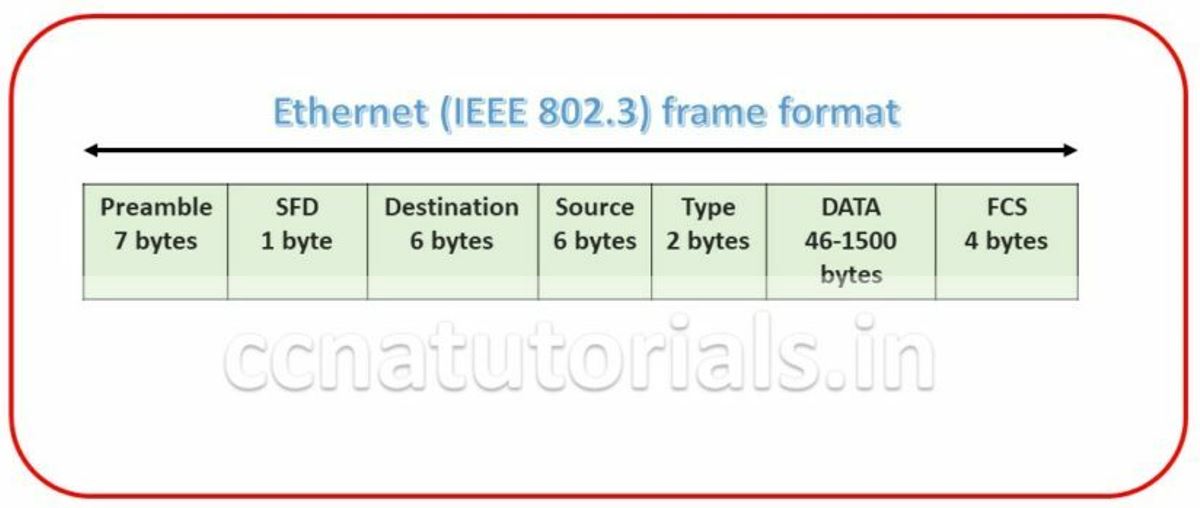
Ethernet frame format is very important term for Ethernet IEEE standard in networking. Bits combined to bytes and bytes to frames at data link layer. The image below show the Ethernet Frame format. The Frames encapsulates packets at data link layer. Ethernet stations pass the data frames in the form of MAC frame format. This provides error detection from a cyclic redundancy check (CRC). This is error detection only, not an error correction. See the below diagram detail of each section following
Preamble for Ethernet Basic concept in Networking
Preamble is the first section of 7 bytes in a frame. The first seven bytes of the preamble are all the same 10101010. Only one bit even the start one or last one is slightly different like 10101011. The 8 bytes of the preamble and the Start of Frame create a pattern of 64 bits. They are not officially counted as part of the Ethernet frame. The frame begins immediately after the Start of Frame, without a gap. An alternating 1, 0 pattern provides a clock rate at the start of each packet. This allows the receiving devices to lock the incoming bit stream.
Start Frame Delimiter (SFD) for Ethernet Basic concept in Networking
The preamble is seven octets and the SFD is one octet. An Ethernet frame starts with preamble followed by the SFD. The actual frame data starts after the SFD. All Ethernet frames starts with the same SFD delimiter, which followed by data unique to the frame.
Destination for Ethernet Basic concept in Networking
It is the 48 bits MAC address of the destination. Destination address used by receiving devices to determine the correct destination. By checking the MAC address of device and Destination this work done. This destination addresses also used for broadcasting or multi-casting data in a network. ff:ff:ff:ff:ff:ff is Ethernet Broadcast address.
Source for Ethernet Basic concept in Networking
The source is similar to destination of 48 bits. It is also a MAC address of the source of data transmitting device. These 48 bits source address identifies the sender device. This address can not be all 1s. It is a single addressee MAC address.
Type for Ethernet Basic concept in Networking
802.3 uses a Type or length field, but the Ethernet-II frame uses a Type field only. Type field used to identify the Network layer protocol. Network layer protocol may be TCP, UDP or IPX etc.
Data for Ethernet Basic concept in Networking
This segment of 46 – 1500 bytes contains the information. This part of the frame will change for each packet. The information required to transmit saved in this section. This packet sent down to the Data Link layer from the Network Layer.
Frame Check Sequence (FCS) for Ethernet Basic concept in Networking
FCS is the last segment of a frame. It is 4 bytes long only. FCS used to store the cyclic redundancy check (CRC) reply. The CRC algorithm run when each frame built based on the data in the frame. The answers of CRC checked at the receiving station. If the CRC answers not found same the fame discarded and original frame re-transmitted again.
Ethernet IEEE standard for Ethernet IEEE standard in networking
The Institute of Electrical and Electronics Engineers Standards Association (IEEE-SA) is an organisation. IEEE develops global standards for technology. Ethernet standard are also developed by this institute. Some predefined Ethernet IEEE standard in networking are following.
10Base-T (IEEE 802.3) standard for Ethernet basic concept in networking
10BaseT is an IEEE standard. The 10BaseT standard denotes the Ethernet connector’s speed is 10 Mbps. 10BaseT connector is base of IEEE 802.3 committee. It uses CAT-3 UTP. It’s maximum distance to run data is 100 meters without data lose. This will provide the connectivity to a host with a wire.
100Base-TX (IEEE 802.3u) standard for Ethernet IEEE standard in networking
100Base-TX is a IEEE standard. this standard denotes the Fast Ethernet at physical layer in a network. It is a twisted pair copper wire connector. 100BaseTX provides data transfer speed up to 100 Mbps. The maximum data traveling length without any loss is 100 meters. 100BASE-T often referred to as Fast Ethernet. The 100BASE-T standard is IEEE 802.3u.
100Base-FX (IEEE 802.3u) standard for Ethernet IEEE standard in networking
A 100 Mbps Ethernet standard denoted the optical fibers connector. 100Base-FX known as IEEE 802.3u standards. It provides 100 Mbps data flow speed up to 1-mile approx.100Base-FX uses central SC, ST or MIC connectors. It provides point to point topology.
1000Base-CX (IEEE 802.3z) standard for Ethernet IEEE standard in networking
1000Base-CX also known as Gigabit Ethernet port. It provides 1 Gbps speed over the Ethernet at physical layer in a network. It is also known at high speed serial data connector.
1000Base-T (IEEE 802.3ab) standard for Ethernet IEEE standard in networking
1000Base-T is a four pair copper wire Ethernet connector. It provides data flow speed upto 1Gbps. The maximum distance for data flow without loss in 100 meters. Generally Cat5 and Cat6 cable are use for 1000Base-T ethernet connector.
1000Base-SX (IEEE 802.3z) standards for Ethernet IEEE standard in networking
1000Base-SX belongs to IEEE 802.3z standards. It is replacement of 1000Base-T copper wire cable. Generally It provides 1000 Mbps or 1 Gbps through the optic fiber cable. It provides connectivity upto 1000 meter on the same data flow speed.
1000Base-LX (IEEE 802.3z) standard Ethernet IEEE standard in networking
The LX in 1000BaseLX stands for long. it is also known as Gigabit Ethernet. The data flow through optic fiber cable for 1000Base-LX Ethernet. It is single mode fiber cable. It can provides the data flow up to 10 kilometers without any data lose.
1000Base-ZX standards for Ethernet IEEE standard in networking
1000BaseZX is a Cisco specified standard for Gigabit Ethernet communication. It provides data flow speed up to 1 Gbps for a maximum distance up to 70 km.
10GBase-T (802.3.an) Ethernet IEEE standard in networking
A proposed network for data speed up to 10 Gbps. It will use copper wire cat5 and cat6 cables. It will also supposed to work up to 100 meters via RJ45 connector Ethernet.
In this article I describe the Ethernet IEEE standard in networking including some basic terms related to Ethernet basics in networking. I hope you found this article helpful. For any suggestions or query on this article you may contact us. We always welcome your suggestions.
Like!! Thank you for publishing this awesome article.