
In this article I describe about OSI reference model in computer network for CCNA exam. OSI reference model in computer network followed by all the manufacturer to provide the compatibility among the various hardware. There are many manufacturer of computer machine in the market. Initially When computers became single user public computer. The computers communicate with only same brand machines. It happens because there was no any fix standard for data transfer between different devices. It is very difficult to make communication with each other when the hardware are of different brands or company.
OSI reference model in computer network followed by various vendors to overcome this problem. After implementation of OSI reference model in computer network, equality maintains by all manufacturer. In 1970 the Open Systems Interconnection (OSI) reference model was created by the International Organization for Standardization (ISO). The OSI model was meant to create inter-operable network with different manufactured devices. In this article I describe all layered approach of OSI reference model in computer network.
Importance of OSI reference model in computer network
Not only hardware, software also not supported for work the different computer brand. It became very difficult for all computer users to working without implementation of OSI reference model in computer network. It is necessary then to make some common protocols for all vendors of computer. Before implementation of OSI reference model in computer network, all vendors implements their own protocols on computer hardware and software.
In networking OSI reference model became helpful. OSI reference model describes the flow of data between nodes in any network. Data from one computer application to another computer application transfer by following some common protocols. The OSI reference layer also become beneficial for troubleshooting the network problems. TCP/IP and Three layered hierarchic model of Cisco became more helpful alongside the OSI reference model.
The Layered Approach for OSI reference model in computer network.
The Layered approach was the best way to make equality for all computer devices. Layers are not physical but following some protocols. Protocols are for connectivity, connections, data transfer and more. All manufacturer begin to follow the layered approach for OSI reference model in computer network. Later in the briefing of OSI layer architecture article we approach layers briefly. Later the OSI reference model change in TCP/IP reference model. OSI layer architecture have 7 layers. TCP/IP reference model convert these 7 layers into only four layers.
OSI reference model in computer network in detail
OSI is acronym for open system interconnection. The OSI is a logical reference OSI reference model in computer network. OSI model helps for data flow between different devices and operating systems. All manufacturer used their own architecture before invention of OSI reference model. It was very difficult to establish data communication between different devices. To overcome this problem international organization for standardization (ISO) created the open systems interconnection (OSI) reference model. OSI reference model make data flow possible between different operating system, devices and hardware.
Structure of OSI reference model in computer network
OSI reference model in computer network consist of 7 layers. These 7 layers further divided into two groups. First 3 layers works for application communication and remaining 4 layers works for data flow. Application, presentation and session layers define the application communication. Transport, network, data link and physical layers define the data flow. Networking protocols works only on last four layers.
Layers of OSI reference model in computer network
Below image shows the seven layers of OSI reference model. Transmit and receive side shown in diagram.
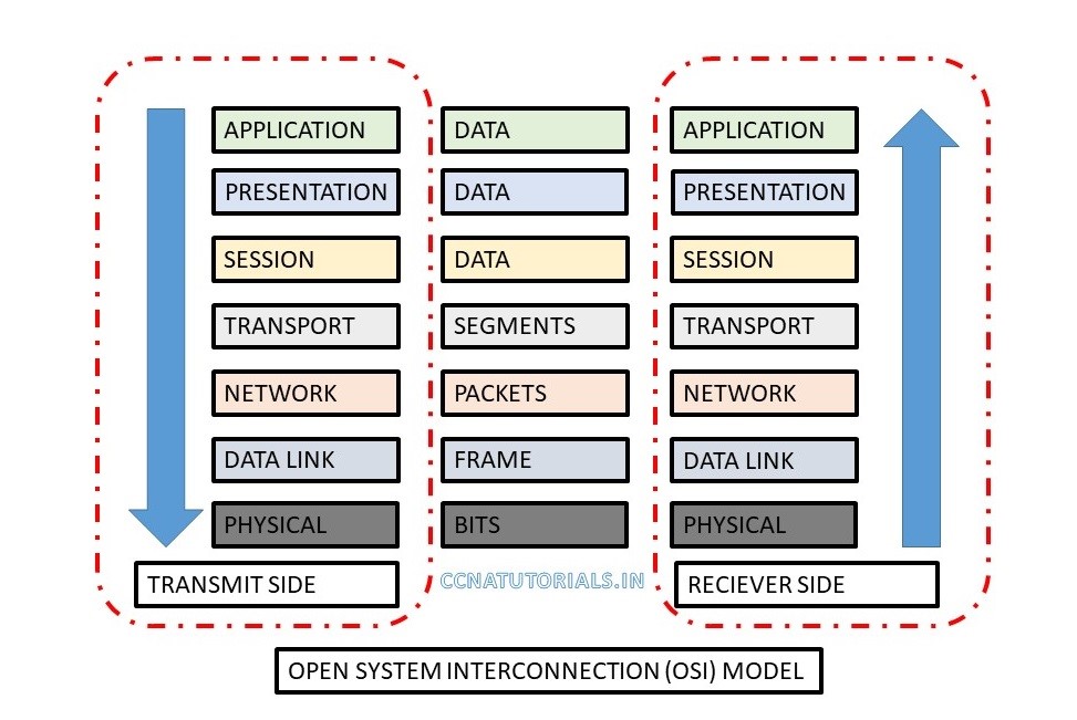
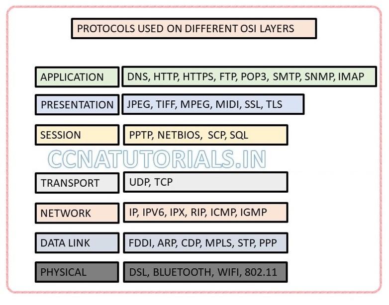
Let’s take an example of email sending and receiving. There are two users for email flow on internet. A sender composes and send mail at application layer. At transmit side data flow from application to physical layer. Physical media carry the data for receiver. At receiver end data flow from physical to application layer. At application layer receiver got the email. During this process a lots of protocol functions. In above diagram some protocols example shown at various layers.
The application layer in OSI reference model in computer network
Application layer provides interface to user for working on a computer. Take an example of outlook emailing application. What a user can see on the computer screen is the application layer functionality. Application layer also interact with the presentation layer. Some examples of application layer are internet browsing, email, file transfers, work on remote computer, printing etc. Standalone software or application like notepad doesn’t lie in OSI reference model. The main function of application layer is to provide an interface to user for Working on computer. Some common protocols work on application layer are DNS, HTTP, HTTPS, FTP, POP3 etc.
The presentation layer in OSI reference model in computer network
Presentation layer works as a translator for data. Presentation layer translate the data in prescribed format for user. At sender computer presentation layer translate the data received from application layer. This translated data forwarded to session layer. At receiver computer reverse process done at presentation layer. The best example of translation in converting the ASCII code into EBCDIC code.
Presentation layer also responsible for data compression in OSI reference model in computer network, encryption and decryption etc. suppose a user is watching online video. The data translated to required video format. Similarly, for image data converted to required format like jpeg, tiff etc. Presentation layer integrate all formats of data into a standard format. The presentation layer translates data of application layer to network format The presentation layer is responsible for the following:
- Data encryption/decryption
- Character/string conversion
- Data compression
- Graphic handling
The session layer in OSI reference model in computer network
Function of session layer is to manage and maintain session between client to client. Session layer make and close the session between two end devices. PPTP, SQL are protocols used by session layer. Some common functions for session layer are dialog control, Token management, synchronization. This layer maintain session in the form or simplex, half-duplex and full duplex. Simplex transmission is one side transmission. Half-duplex is both side transmission but one side at a time. Full duplex is both side transmission in real time like telephone.
The transport layer in OSI reference model in computer network
TCP and UDP protocols are integral to transport layer in OSI in computer network. Transport layer create segments of the data stream received from presentation later at transmission stage. At receiver stage transport layer assemble the segments and send the data stream to presentation layer. Transport layer establish a logical connection between the end equipment on an internetwork. The Transport layer is responsible for multiplexing upper layer applications, create sessions, sequencing data, acknowledgments etc.
Transport layer works on connection oriented communication. It is reliable for data transmission. In connection oriented communication first step is handshake. After handshaking data transfer starts until the complete data transferred. If data transferring using TCP protocol, then acknowledgment of complete data transfer is must. In case complete data not transferred same data re-transmit again. Data flow depends on speed of the network. During transfer the data congestion can occur. To overcome data congestion flow control term used. Flow control ensure data integrity at transport layer. Data overflowing and buffers prevented by flow control.
Connection oriented communication uses sequencing, acknowledgements, flow control, congestion control and windowing. When a device send data and doesn’t need acknowledgement, it is called windowing. Online video uses windowing. Window size defined when the acknowledgement required. Suppose you set the window size 2. For window size 2 transmitting computer will check acknowledgement after every 2 segments transmitted. Minimum the windowing size increase the congestion because acknowledgment required more.
The network layer in OSI reference model in computer network
Network layer commonly known as layer 3. Network layer works on IP address system. OSI reference is fully depends on network layer. Segments received from transport layer breaks in packets and forwarded to data link layer. Similarly, packets reassembled received from data link layer and forwarded to transport layer. Routers are layer 3 devices. Router configured at layer 3 for OSI reference between different LANs.
IP, IPv6, IPX, RIP protocols functions on layer 3 or network layer. Protocols used for data traffic at layer 3 are called routed protocol. Whereas protocols used to keep update the routing table of neighboring router are called routing protocol.
Suppose a packet received on a router interface. Router will check the destination address on this packet. Router check it’s ip address in routing table and forward it to related exit interface. If router doesn’t have the destination address in its routing table, then router will drop the packet. There are Route update packets used to keep update the neighboring router. Router maintain individual routing protocol for each protocol.
Router doesn’t send any broadcast or multicast packet itself. The Router use a logical address in a network layer header to forward a packet. Access list used by router to keep control security. Routers provide connections between virtual LAN.
The data link layer in OSI reference model in computer network
Data link layer works on frame in a OSI in computer network. Packets received from network layer breaks into frame at data link layer during transmission of data. Frame constructed the packets and forwarded to network layer during receive data. some protocols used at data link layer are FDDI, PPP etc. data link layer also convert the frame into bits and send to physical layer and vice versa. Every frame adds a header which contains the destination and source address. Data link layer use the MAC address or source and destination. It never uses the IP addressing system.
IEEE standards divide the data link layer into two parts. One is Media Access Control (MAC) and other one is Logical Link Control (LLC).
Media Access Control MAC defines to place the packet on the media. Its basic principal is first come first serve. Synchronization, error notification, delivery of frames and flow control also used at MAC. Logical link control (LLC) identifies the network layer protocols.
LLC header define the task of data link layer for a packet. Switch and bridge works on data link layer. Latency is the time measured from when a frame enters a port to when it exits a port. Switch maintain a MAC address table to transfer a packet to its destination. Layer 2 devices works on frame only. These devices forward frames only.
When a switch received a frame, it will check the header of frame for MAC. Switch check its mac address table for destination MAC address. If MAC address found, then switch forward the frame to destination. If MAC address not found switch broadcast the frame to each port. On receiving reply from any port switch will update its MAC address table accordingly.
The physical layer in OSI reference model in computer network
Physical layer transmits and receive bits. Bits are only two value. At physical layer it may be 0 and +5v. we can say them as high and low volts. Physical layer connect links between the end devices. Link may be electrical, optical, DSL, WiFi etc. Hubs are layer 1 device which works on physical layer. The Hubs are simple repeater.
Hubs receive amplify and transmit the bits to all ports. Physical layer also defines the network topology. Every network has both physical and logical typologies. Logical topology is the path of data via which the data flow over the physical topology.
In this article I describes the internetworking model in computer network for CCNA exam. The layered approach reference also described in details. I hope you found this article helpful. For any query or suggestion you may drop a comment below or contact us. Your suggestions are always welcome by us.


A formidable share, I just given this onto a colleague who was doing slightly evaluation on this. And he in fact purchased me breakfast because I found it for him.. smile. So let me reword that: Thnx for the treat! However yeah Thnkx for spending the time to debate this, I really feel strongly about it and love reading extra on this topic. If attainable, as you develop into experience, would you thoughts updating your blog with more details? It’s extremely useful for me. Huge thumb up for this blog publish!