In this article I describe the internetworking basics in CCNA exam 200-301. CCNA exam need the complete knowledge of router and switch configuration. Internetworking basics in CCNA consist the working of networking devices. The process of connecting different networks by some intermediate devices is known as internetworking. In this article I describe the basics of switch, hub, router along with broadcast domain and collision domain.
Internetworking allows data and voice communication between different networks. Routers are used as intermediate devices between different networks. A lots of protocol used to provide data and voice communication between different networks. Internetworking works on some predefined model like OSI layer model and TCP/IP model. Another model is three-layer hierarchical model of Cisco.
Before going to the internetworking let’s remember about computer network. A computer network is a combination of various computers connected together for sharing the network resources. Switch and hubs provide connectivity to the computers to share resources in a network. IP address system used to identify the computer in network for data communication. We can say switches used in networking and router used for internetworking. Routers are physical hardware devices allow to connect different networks.
Introduction to Internetworking basics in CCNA
Networking is the base of internetworking basics. Before going to deep for internetworking basics in CCNA the concept of networking should be well known. In networking different devices are connected with some switches only. The data flows within the network nodes in a LAN. The concept of internetworking comes when we need to transfer the data from outside of LAN. For example, internet when we need to access internet from our local network the traffic come from outside the LAN. This function is possible because of connectivity or different networks via routers. Internetworking means access to different networks from different networks.
Multiple protocols work between different networks to provide connectivity. Some of important protocols are Transfer Control Protocol TCP and Internet Protocol IP. Some routing protocols like RIP, OSPF etc works in router for IP routing in router. IP routing provides the data flow between different networks in internetworking. Three terms are related to internetworking basics in CCNA Internet, Intranet and Extranet. So lets discuss about these three terms in detail below.
Internet – We all works on internet. Internet is the best example to understand the internetworking basics in CCNA. Billions of networks are connected on internet and we all access the multiple websites and services from our LAN. Many big company like google, Microsoft maintains their LAN and provide a gateway to enter and exit the data packets from there. There are many services provided by the data centre of these companies like email, drive etc to keep and share the data. There are multiple routers works on different protocols to connect the internet world wide.
Intranet – Intranet is very similar to the internet. The only difference is that the access of intranet network is allowed to some limited persons only. The physical layout of intranet is same as internet locations. By using some special protocols and private IP addresses the access of intranet computers is not allowed to any public computer like internet. The example of intranet is any private organization which have main office at a fix place and the branches are located at various different locations. The client of the organisation can access the data centre services. A common computer of internet cannot access the services of private organization from internet. Example of intranet is the army network of any country.
Extranet- extranet is the advance version of intranet. In intranet only single organization can access the private network. Extranet provide multiple intranet to communicate with each other over the internet. I mean the user of one organization can access the data of other organization. The data of extranet is not allowed access to public on the internet. Multiple intranet creates an extranet on the internet.
Address system of internetworking basics in CCNA
Different types of address systems available for internetworking basics in CCNA. Addressing system provide the identity to the networks and computers in internetworking. When data transfers from one network to another network three different address works. The three address systems are Data Link Layer address, MAC address and network layer address. I give some basic Idea about these three address types necessary for internetworking basics in CCNA.
Data Link Layer address for internetworking basics in CCNA
Data link address identifies all the networks connected with the router. Suppose there are three networks connected with a router on different interface. The network address of each network connected with the router is known as Data link address. Router knows what network addresses are connected with it and forward the packets according to data link address associated with each interface. End point devices connected with single network address, so all End point devices maintain a single data link address associates with them. Routers usually have multiple physical network connections so eventually have multiple data-link addresses.
MAC address for internetworking basics in CCNA
MAC address is known as the physical address of a device. Every device which can connected with network have it’s own MAC address. MAC address is a 48 bit long hexadecimal combination. In a LAN the MAC address identified by the switch. The data forwarded on the basis of MAC address of connected devices. Some digits of the MAC address present the organization by OUI. OUI stands for Organizational Unique Identifier. Some digits of the MAC address present the merchant or vendor of the hardware. In a LAN the switch forward the data packets according to the MAC address of devices.
Network Layer Address for internetworking basics in CCNA
Network layer address referred as virtual or logical addresses. Generally, the network layer address known as the network address or IP address. The network and internetworking works on IP address system of networking devices. The IP addresses are of two types IPv4 and IPv6. IP routing is depending on IP addresses of network. A router may be connected with multiple networks with its interfaces. The IP packets routed according to the network ID attached with it.
Broadcast domain for internetworking basics in CCNA
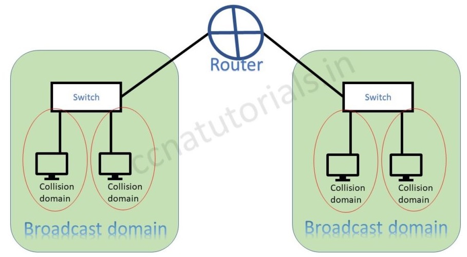
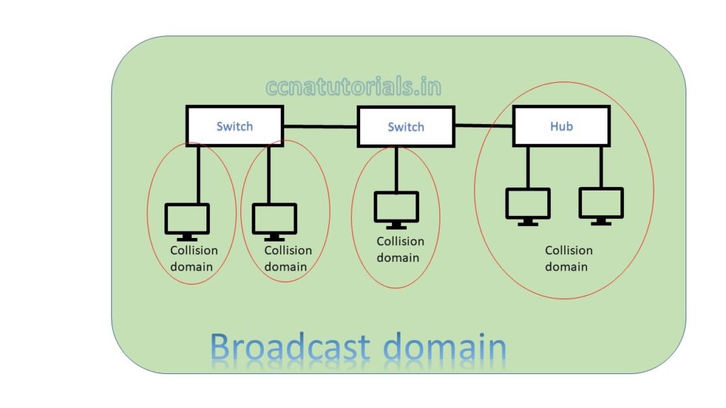
A broadcast domain is the domain in which broadcasting done. Broadcasting takes place on data link layer. All the devices which works on data link layer have single broadcast domain. All ports of a hub belongs to a single broadcast domain. Similarly all ports of a layer 2 switch also in a common broadcast domain. Router works on layer 3 hence all ports of a router in different broadcast domain. Below picture explain broadcast domain better.
Broadcast domain defines the boundary of data broadcasting. All ports of a switch belong to a single broadcast domain. Each port of a switch breaks the collision domain and create its own collision domain. Each port of a router breaks the broadcast domain. The port of a router have its own broadcast domain. Further switch uses to break the collision domain. In a broadcast domain device communicate via Data Link Layer.
The below picture shows the difference of broadcast and collision domain. Switch breaks collision domain and router breaks the broadcast domain.
Switch can break the broadcast domain logically via creating VLAN. A router creates broadcast domain boundaries. The size of broadcast domain is responsible for performance of network. It is good to keep the broadcast and collision domain as small as possible. This practice will improve the network performance also data flow speed. I hope in Ethernet basic concepts relation of broadcast and collision domain is clear now.
Collision domain for internetworking basics in CCNA

Collision domain term related to hub or physical layer devices. Hub use a common media to send and receive the data. Hub works as a shared media in an Ethernet network. Data flow on a single media and collapse several times. This is the reason of collision and the devices belongs to this network are lie in a common collision domain. Bus topology is the best example of collision data. Bus topology and Ethernet hub are half duplex. These devices can send or receive data at the same time.
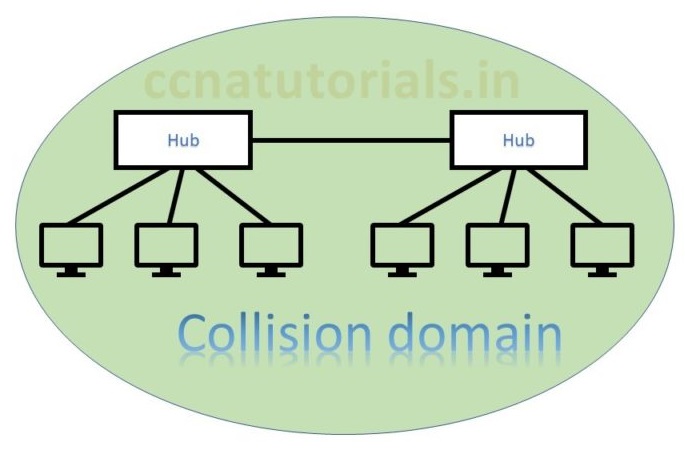
In above picture two hubs are connected with each other. Both hubs are in a common collision domain. Hub works on physical layer transmit the data to all connected devices. This is why collision occurs. In this scenario data lost generally and the sender must resend the data. Data collision responsible for poor network performance. In Ethernet basic concepts collision domain and broadcast domain are basics.
In above picture two switch creates a network. Both switch and connected device are in a single broadcast domain. Each port of switch itself creates a separate collision domain. There are four collision domains. All devices connected with a Hub remains in a collision domain.
According to both above pictures we can say a switch breaks collision domain. Switch can not break a broadcast domain, so all ports of a switch belongs to a broadcast domain. By using switch in place of hub the collision domains break and performance of network improved.
Function of HUB for internetworking basics in CCNA
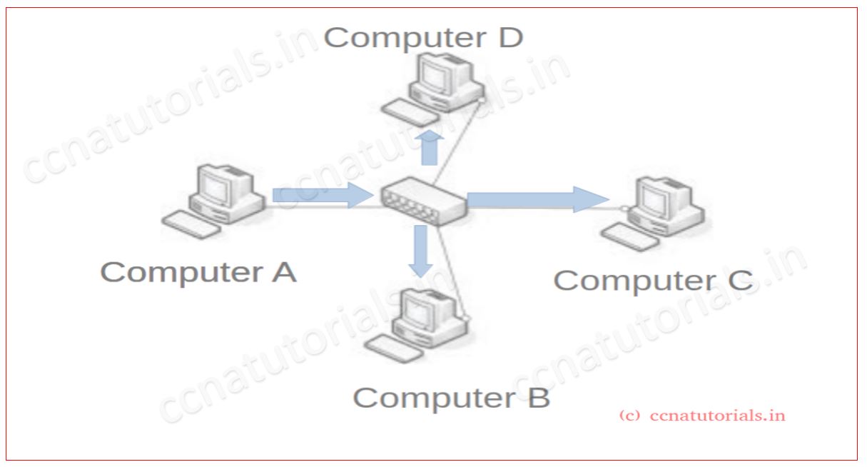
Consider a basic network which connected four computers via HUB. As shown in above figure. We know that all ports of a hub in a single broadcast and in single collision domain. In this network computer A want to send a packet for computer B. When computer A transmit the packet then hub transmit the same packet for all computers except the sender. In this scenario if all computer wants to communicate with each other, then a chances of data lost are maximum. There is no any acknowledgement of data receive. To overcome this problem switch used in a LAN. Switch breaks up the collision domain.
Function of Bridge for internetworking basics in CCNA
Bridge introduced before router and switches. bridge do the same thing like a hub. A bridge breaks the collision domain in a network. in today’s scenario bridges are mostly outdated. Managed switch commonly used for LAN.
Function of Switch for internetworking basics in CCNA
Now consider a network as shown in below picture. Here four computers connected with a switch. All computers in one broadcast domain. Each computer is in distinct collision domain. We can say in this network there are one broadcast domain and four collision domain. A switch breaks up the collision domain.
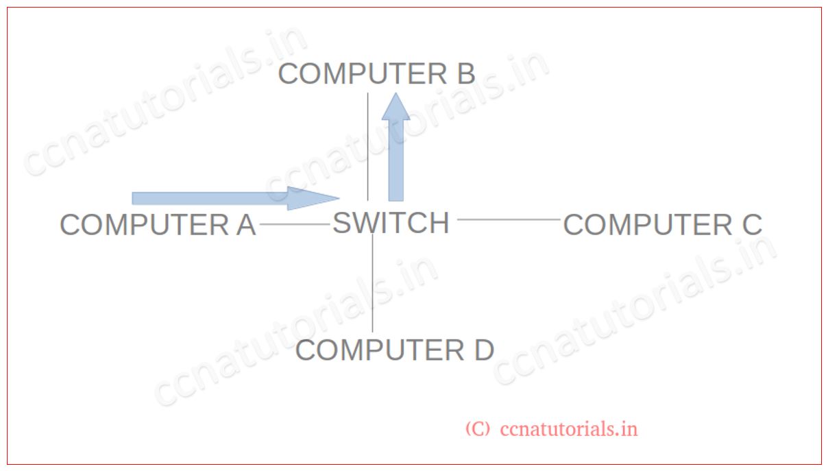
In above network computer A wants to send some data to computer B. Switch have a MAC table in its database. On checking the packet received from computer A. It can found that the destination is computer B. Switch will transmit this packet for computer B only. Data lost minimised in this network.
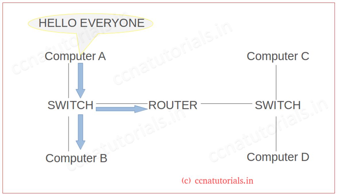
Function of Routers for Internetworking basics in CCNA
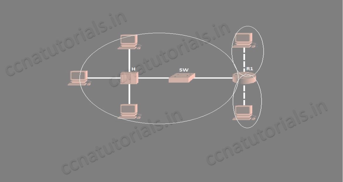
Consider a Network as shown in below figure. Router breaks up the broadcast domain. This network have two broadcast domains for each port of router. Computer A can communicate with computer B as both in same broadcast domain. Computer A send data for all nodes of its network. switch transmit the data from all ports. when router received the data. It will deny it. So computer C and D did not receive the data of computer A. If computer A want to send data for computer C or D then router will pass the data through it. I hope you understood the Importance of breaking up a broadcast domain.
Router can filter layer 3 (Network layer) information such as an IP address. Routers can do packet filtering via access lists. Router connects two or more networks by using logical addressing. Routers use routing table for logical addressing. Routing table also used for selection of best path for packets.
Layer 2 switches can not used for internetworking because all switch ports belongs to same broadcast domain. Switches used to overcome the problem of HUB. Switch forward only frames from one port to another port. Switching done in a router. Virtually switch also break the broadcast domain. this process called VLAN.
In this article I describe the internetworking basics for CCNA exam. I hope you found this article helpful. For any query or suggestion, you may drop a comment below or contact us. Your suggestions are always welcome by us.

This web site is really a walk-through for all of the info you wanted about this and didn’t know who to ask. Glimpse here, and you’ll definitely discover it.