In this article, I describe the Ethernet at Data Link Layer in Networking for CCNA Exam. Ethernet at data link layer in networking is main part of learning the networking. Ethernet provides connectivity to the networking devices in a network. An Ethernet provides physical connectivity for data transfer in a network. There are various standards of Ethernet available according to the speed and reliability.
Ethernet works on Data link and physical layer of OSI reference model. Ethernet at data link layer concept in networking related to access the media from a device. The Ethernet provides connectivity between nodes and different networking devices. Ethernet connector is well known as RJ45 connector. Implementation and maintains of Ethernet is very easy. Ethernet port provides speed up to gigabits per second. Ethernet is responsible for formatting and transmission of data in a predefined format. Similarly, at the receiver end the received data reformatted in a predefined format.
Working of Ethernet: Ethernet at data link layer in Networking
Ethernet belongs to IEEE standard IEEE 802.3 family. Ethernet at data link layer in networking, Ethernet working depends on both physical and data link layer. The Ethernet send and receive the bits and frame in a network. Physical layer defines the bits streaming and data link layer defines the frame streaming. Ethernet is responsible for VLAN tagging, QOS, error correction and identify the transmission problems. An Ethernet do work metallic conductor cables. Ethernet cable may be co-axial, twisted pair or CAT-6 cables.
Collision Domain and Broadcast Domain depends on Ethernet protocols. Collision and broadcast domain define by the connectivity media like hub, switch etc. The Collision and Broadcast domain defined at different layers of OSI model.
Half- and Full-Duplex Ethernet basic concept in networking
IEEE 802.3 standard identify the half duplex Ethernet. In half duplex Ethernet the data flow one side at a time. Suppose two devices are connected with half duplex Ethernet. At one time only one device can send the data. Half duplex Ethernet uses the CSMA/CD protocol. Collision occurs in half duplex Ethernet network. A hub relates to a switch works like a half-duplex Ethernet network. Data flow speed is very low in a half-duplex network due to collision.
Half-duplex Ethernet network uses one pair wire for flow of data in the network. Full-duplex Ethernet works on two pair wire. Full-duplex Ethernet uses point to point connections between sending and receiving device. Full duplex Ethernet network works like a telephone communication. Simultaneously data send and receive in a full-duplex network. Data flow speed is fast in a full-duplex Ethernet network than half-duplex Ethernet network. Each device has its own collision domain in full-duplex Ethernet network. CSMA/CD protocols used in full-duplex Ethernet network. Full-duplex Ethernet are switch-to-switch, host to host, router to router, switch to host, switch to router etc.
Ethernet Addressing: Ethernet at data link layer in Networking
Ethernet addressing is identification of Hardware. A unique MAC address is assigned to each network interface card. NIC may be physical media or wireless media. MAC address is acronym for Media Access Control. IEEE standard gives a format of MAC address as shown in figure below. This format should be followed by every hardware maker. By following the format any manufacturer NIC can communicate with each other.
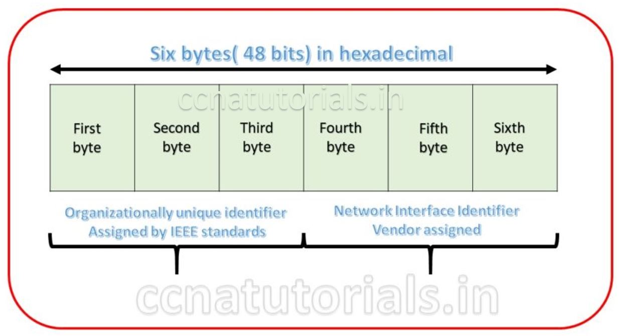
MAC address is a combination of six bytes in hexadecimal format. MAC address written once on NIC cards when it manufactured. 48 bits divided in six octet section. 24 bits assigned for organisationally unique identifier (OUI). OUI assigned by the IEEE to an organisation.
Individual group bit and Global local bit
The very first two bits are known as individual group bit and Global/Local bit. Individual group bit identifies the ethernet whether it is source portion or broadcast/multicast address. Individual group bit 0 denotes the source portion and bit 1 denotes it is broadcast/multicast address. The next one is Global/Local bit also known as G/L bit. G/L bit denotes whether the MAC address is globally address assigned by IEEE or it is local address. When G/L bit 0 tells the MAC address is globally address and bit 1 tells that the MAC address is locally address only. Next three bytes are assigned by vendor. The vendor-assigned portion of the MAC address is just that, the alphanumeric identifier assigned by the vendor.
Frame Format for Ethernet at data link layer in Networking
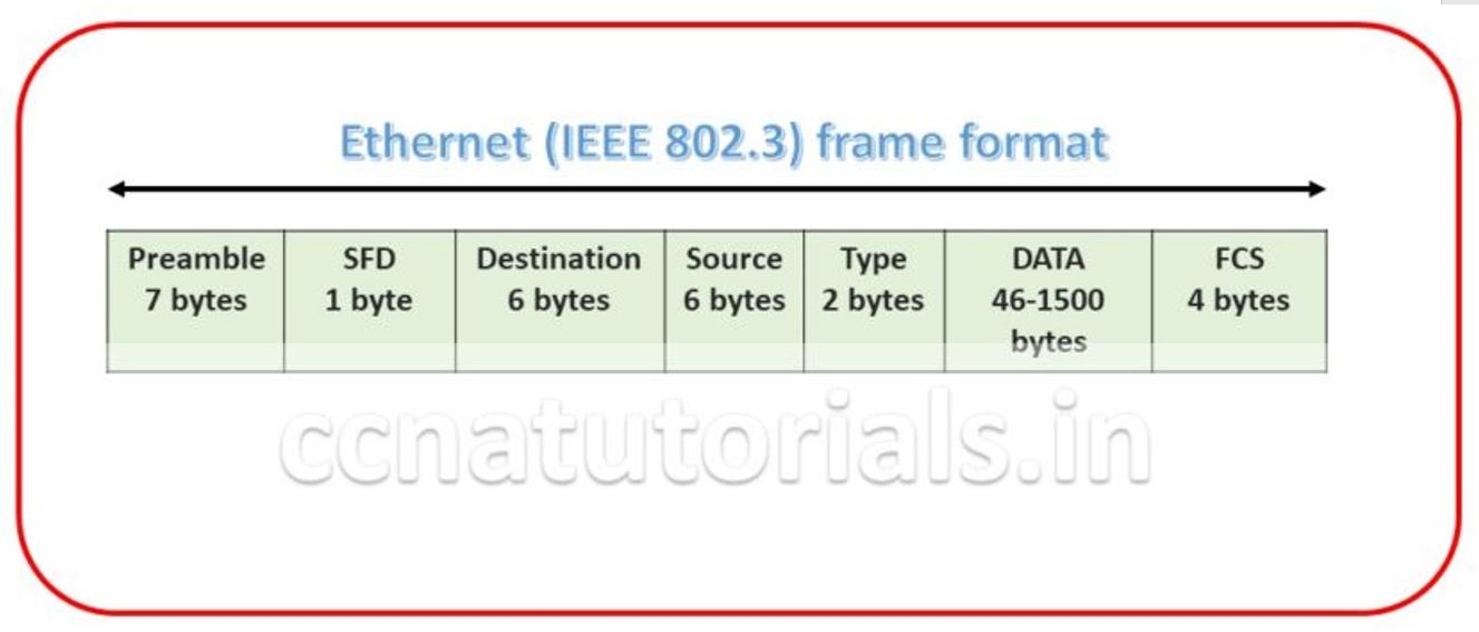
Ethernet frame format is very important term in Ethernet at data link layer in networking. Bits combined to bytes and bytes to frames at data link layer. The image below show the Ethernet Frame format. The Frames encapsulates packets at data link layer. Ethernet stations pass the data frames in the form of MAC frame format. This provides error detection from a cyclic redundancy check (CRC). This is error detection only, not an error correction. See the below diagram detail of each section following
Preamble for Ethernet at data link layer in Networking
Preamble is the first section of 7 bytes in a frame. The first seven bytes of the preamble are all the same 10101010. Only one bit even the start one or last one is slightly different like 10101011. The 8 bytes of the preamble and the Start of Frame create a pattern of 64 bits. They are not officially counted as part of the Ethernet frame. The frame begins immediately after the Start of Frame, without a gap. An alternating 1, 0 pattern provides a clock rate at the start of each packet. This allows the receiving devices to lock the incoming bit stream.
Start Frame Delimiter (SFD) for Ethernet at data link layer in Networking
The preamble is seven octets and the SFD is one octet. An Ethernet frame starts with preamble followed by the SFD. The actual frame data starts after the SFD. All Ethernet frames starts with the same SFD delimiter, which followed by data unique to the frame.
Destination for Ethernet at data link layer in Networking
It is the 48 bits MAC address of the destination. Destination address used by receiving devices to determine the correct destination. By checking the MAC address of device and Destination this work done. This destination addresses also used for broadcasting or multi-casting data in a network. ff:ff:ff:ff:ff:ff is Ethernet Broadcast address.
Source for Ethernet at data link layer in Networking
The source is similar to destination of 48 bits. It is also a MAC address of the source of data transmitting device. These 48 bits source address identifies the sender device. This address can not be all 1s. It is a single addressee MAC address.
Type for Ethernet Networking
802.3 uses a Type or length field, but the Ethernet-II frame uses a Type field only. Type field used to identify the Network layer protocol. Network layer protocol may be TCP, UDP or IPX etc.
Data for Ethernet at data link layer in Networking
This segment of 46 – 1500 bytes contains the information. This part of the frame will change for each packet. The information required to transmit saved in this section. This packet sent down to the Data Link layer from the Network Layer.
Frame Check Sequence (FCS) for Ethernet Basic concept in Networking
FCS is the last segment of a frame. It is 4 bytes long only. FCS used to store the cyclic redundancy check (CRC) reply. The CRC algorithm run when each frame built based on the data in the frame. The answers of CRC checked at the receiving station. If the CRC answers not found same the fame discarded and original frame re-transmitted again.
Ethernet IEEE standard for Ethernet at data link layer in networking
The Institute of Electrical and Electronics Engineers Standards Association (IEEE-SA) is an organisation. IEEE develops global standards for technology. Ethernet standard are also developed by this institute.
10Base-T (IEEE 802.3) standard for Ethernet at data link layer in networking
10BaseT is an IEEE standard. The 10BaseT standard denotes the Ethernet connector’s speed is 10 Mbps. 10BaseT connector is base of IEEE 802.3 committee. It uses CAT-3 UTP. It’s maximum distance to run data is 100 meters without data lose. This will provide the connectivity to a host with a wire.
100Base-TX (IEEE 802.3u) standard for Ethernet at data link layer in networking
100Base-TX is a IEEE standard. this standard denotes the Fast Ethernet at physical layer in a network. It is a twisted pair copper wire connector. 100BaseTX provides data transfer speed up to 100 Mbps. The maximum data traveling length without any loss is 100 meters. 100BASE-T often referred to as Fast Ethernet. The 100BASE-T standard is IEEE 802.3u.
100Base-FX (IEEE 802.3u) standard for Ethernet at data link layer in networking
A 100 Mbps Ethernet standard denoted the optical fibers connector. 100Base-FX known as IEEE 802.3u standards. It provides 100 Mbps data flow speed up to 1-mile approx.100Base-FX uses central SC, ST or MIC connectors. It provides point to point topology.
1000Base-CX (IEEE 802.3z) standard for Ethernet at data link layer in networking
1000Base-CX also known as Gigabit Ethernet port. It provides 1 Gbps speed over the Ethernet at physical layer in a network. It is also known at high speed serial data connector.
1000Base-T (IEEE 802.3ab) standard for Ethernet at data link layer in networking
1000Base-T is a four pair copper wire Ethernet connector. It provides data flow speed upto 1Gbps. The maximum distance for data flow without loss in 100 meters. Generally Cat5 and Cat6 cable are use for 1000Base-T ethernet connector.
1000Base-SX (IEEE 802.3z) standards for Ethernet at data link layer in networking
1000Base-SX belongs to IEEE 802.3z standards. It is replacement of 1000Base-T copper wire cable. Generally It provides 1000 Mbps or 1 Gbps through the optic fiber cable. It provides connectivity upto 1000 meter on the same data flow speed.
1000Base-LX (IEEE 802.3z) standard Ethernet at data link layer in networking
The LX in 1000BaseLX stands for long. it is also known as Gigabit Ethernet. The data flow through optic fiber cable for 1000Base-LX Ethernet. It is single mode fiber cable. It can provides the data flow up to 10 kilometers without any data lose.
1000Base-ZX standards for Ethernet at data link layer in networking
1000BaseZX is a Cisco specified standard for Gigabit Ethernet communication. It provides data flow speed up to 1 Gbps for a maximum distance up to 70 km.
10GBase-T (802.3.an) Ethernet IEEE standard
A proposed network for data speed up to 10 Gbps. It will use copper wire cat5 and cat6 cables. It will also supposed to work up to 100 meters via RJ45 connector Ethernet.
Data Link Protocols for Ethernet at data link layer
Some common data link protocols related to Ethernet at data link layer are token ring and FDDI protocol. In this section of the article, I describe these two protocols related to Ethernet at data link layer.
Token Ring Protocol for Ethernet at data link layer
Token ring is very old technology which was used in networking. A token passing technology used in for communication in networking earlier which is known as logical token ring topology. Token ring topology is 802.5 IEEE standardized. A device can transmit the data in the network only if the device has a token ring. The device hold the token ring until the confirmation of data received by the destination device. Token ring provides a data packet collision free data flow in the network as at a time only a single device can transmit the data.
FDDI Fibre Data Distribution Interface for Ethernet at data link layer
FFDI protocol works at data link layer. FDDI is a network protocol that can be used as a token passing method in a network. The FDDI supports a data speed upto Gbps on an interface of switch. FDDI provides redundancy and data reliability in a network. The FDDI uses same technology as token ring. It provides a collision free data transfer in a network. The method of data transfer is similar to token ring. A device can transmit the data only if the device have token. The transmission device keep the token until the confirmation of data received by the destination device.
In this article I describe Ethernet at data link layer in networking. I hope you found this article helpful. For any query or suggestion you may drop a comment below or contact us. Your suggestions are always welcome by us.
This is a great tip particularly to those fresh to the blogosphere.
Brief but very precise information… Appreciate your
sharing this one. A must read article!
I am truly happy to glance at this website posts which contains
lots of helpful information, thanks for providing such data.
Howdy I am so excited I found your web site, I really found you by mistake, while I was searching on Aol for something else, Regardless I am here now and would just like to say cheers for a tremendous post and a all round interesting blog (I also love the theme/design), I don’t have time to look over it all at the moment but I have saved it and also added your RSS feeds, so when I have time I will be back to read a lot more, Please do keep up the superb job.
Like!! I blog frequently and I really thank you for your content. The article has truly peaked my interest.