In this article I describe the Ethernet Cabling Types in Networking for CCNA Exam. Ethernet Cabling Types in networking is main part of practical the networking. Ethernet provides connectivity to the networking devices in a network. An Ethernet provides physical connectivity for data transfer in a network. There are various standards of Ethernet available according to the speed and reliability.
Ethernet works on Data link and physical layer of OSI reference model. Ethernet Cabling Types in networking is related to access the media from a device with various types of cables. The Ethernet provides connectivity between nodes and different networking devices. The most popular Ethernet connector also known as RJ45 connector. Implementation and maintains of Ethernet is very easy. Ethernet port provides speed up to gigabits per second. Ethernet is responsible for formatting and transmission of data in a predefined format. Similarly, at the receiver end the received data reformatted in a predefined format.
Working of Ethernet: Ethernet Cabling Types in Networking
Ethernet belongs to IEEE standard IEEE 802.3 family. Ethernet Cabling Types, Ethernet working depends on both physical and data link layer. The Ethernet send and receive the bits and frame in a network. Physical layer defines the bits streaming and data link layer defines the frame streaming. Ethernet is responsible for VLAN tagging, QOS, error correction and identify the transmission problems. An Ethernet do work metallic conductor cables. Ethernet Cabling Types may be co-axial, twisted pair, CAT-6 cables and optic fibre cable.
Collision Domain and Broadcast Domain depends on Ethernet protocols. Collision and broadcast domain define by the connectivity media like hub, switch etc. The Collision and Broadcast domain defined at different layers of OSI model.
Half- and Full-Duplex Ethernet Cabling Types in networking
IEEE 802.3 standard identify the half duplex Ethernet. In half duplex Ethernet the data flow one side at a time. Suppose two devices are connected with half duplex Ethernet. At one time only one device can send the data. Half duplex Ethernet uses the CSMA/CD protocol. Collision occurs in half duplex Ethernet network. A hub relates to a switch works like a half-duplex Ethernet network. Data flow speed is very low in a half-duplex network due to collision.
Half-duplex Ethernet network uses one pair wire for flow of data in the network. Full-duplex Ethernet works on two pair wire. Full-duplex Ethernet uses point to point connections between sending and receiving device. Full duplex Ethernet network works like a telephone communication. Simultaneously data send and receive in a full-duplex network. Data flow speed is fast in a full-duplex Ethernet network than half-duplex Ethernet network. Each device has its own collision domain in full-duplex Ethernet network. CSMA/CD protocols are used in full-duplex Ethernet network. Full-duplex Ethernet are switch to switch, host to host, router to router, switch to host, switch to router etc.
Frame Format for Ethernet Basic concept in Networking
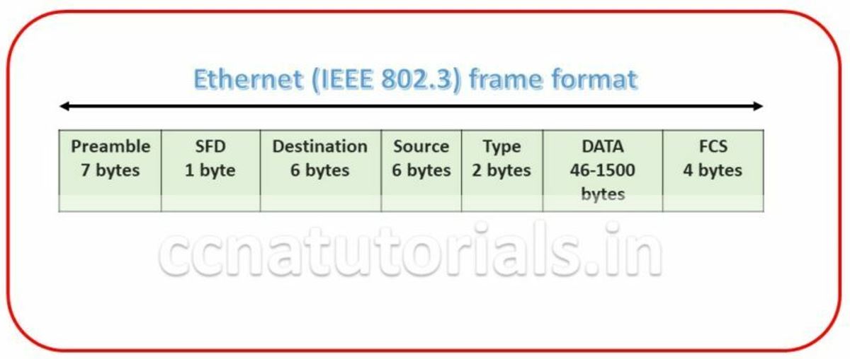
Ethernet frame format is very important term in Ethernet Basic Concept in networking. Bits combined to bytes and bytes to frames at data link layer. The image below show the Ethernet Frame format. The Frames encapsulates packets at data link layer. Ethernet stations pass the data frames in the form of MAC frame format. This provides error detection from a cyclic redundancy check (CRC). This is error detection only, not an error correction. See the below diagram detail of each section following
Preamble for Ethernet Basic concept in Networking
Preamble is the first section of 7 bytes in a frame. The first seven bytes of the preamble are all the same 10101010. Only one bit even the start one or last one is slightly different like 10101011. The 8 bytes of the preamble and the Start of Frame create a pattern of 64 bits. They are not officially counted as part of the Ethernet frame. The frame begins immediately after the Start of Frame, without a gap. An alternating 1, 0 pattern provides a clock rate at the start of each packet. This allows the receiving devices to lock the incoming bit stream.
Start Frame Delimiter (SFD) for Ethernet Basic concept in Networking
The preamble is seven octets and the SFD is one octet. An Ethernet frame starts with preamble followed by the SFD. The actual frame data starts after the SFD. All Ethernet frames starts with the same SFD delimiter, which followed by data unique to the frame.
Destination for Ethernet Basic concept in Networking
It is the 48 bits MAC address of the destination. Destination address used by receiving devices to determine the correct destination. By checking the MAC address of device and Destination this work done. This destination addresses also used for broadcasting or multi-casting data in a network. ff:ff:ff:ff:ff:ff is Ethernet Broadcast address.
Source for Ethernet Basic concept in Networking
The source is similar to destination of 48 bits. It is also a MAC address of the source of data transmitting device. These 48 bits source address identifies the sender device. This address can not be all 1s. It is a single addressee MAC address.
Type of standards for Ethernet Basic concept in Networking
802.3 uses a Type or length field, but the Ethernet-II frame uses a Type field only. Type field used to identify the Network layer protocol. Network layer protocol may be TCP, UDP or IPX etc.
Data for Ethernet Basic concept in Networking
This segment of 46 – 1500 bytes contains the information. This part of the frame will change for each packet. The information required to transmit saved in this section. This packet sent down to the Data Link layer from the Network Layer.
Frame Check Sequence (FCS) for Ethernet Basic concept in Networking
FCS is the last segment of a frame. It is 4 bytes long only. FCS used to store the cyclic redundancy check (CRC) reply. The CRC algorithm run when each frame built based on the data in the frame. The answers of CRC checked at the receiving station. If the CRC answers not found same the fame discarded and original frame re-transmitted again.
Ethernet Cabling Types in detail
Mostly three Ethernet Cabling Types used in a computer network. These three types are important in view of CCNA exam. A lots of networking devices used for creating a LAN. Switches, Hub, Router, Bridge, NIC etc are commonly used in a network. Ethernet Cabling Types are of three types which provides connectivity between networking devices and endpoint devices. I brief each Ethernet Cabling Types in details. The basic Ethernet Cabling Types are Straight-through cable, Crossover cable, Rolled cable and sometimes OFC.
Straight-through and crossover cable generally made of CAT5 or CAT6 cables. Both cables have 4 twisted pair in it. Out of these 4 pairs only two pairs are used for communication in a network. The 4 pairs have distinct colour for identification. CAT5 cable provides data flow speed up to Gigabits per second for a maximum distance of 100 meter. CAT6 cable supposed to provides data flow speed upto 10 Gbps. The purpose of using these different cables is to connect the devices with each other in a network.
Straight Through Cable in Ethernet Cabling Types
Straight through Cable is use to connect the different devices with a common cable for example, host to switch or switch to router. The cable is CAT6 UTP cable the connection types on both ends remain same. As we know there are only two pairs used for communication. Two wires are used for transmitting and other two are for receiving data in a network.
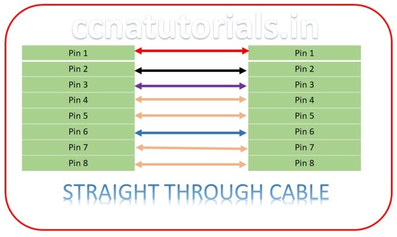
Twisted pair cables are used as straight-through cable in a network to provide connectivity for devices. Generally this cable is known as patch cord which have RJ45 connectors on both end. The 8 pins on both end connectors connected in a similar pattern. This is the very common type of Ethernet Cabling Types which is used in all computer networks frequently.
Crossover Cable in Ethernet Cabling Types
Crossover cable used to connect the similar devices in a network, for example, switch to switch, router to router the reason behind that is the connector pins on both end doing same function. So we need to connect the transmitting pins at one end with receiving pins on the other end. Similar devices have the same pin for transmit data and receive the data. If we use straight through cable between two similar devices, then data can’t be sent from one to another. To overcome this drawback crossover cable created. To make cross over cable we make connections such that the transmit pin one side connects to receive pin another side. Below image show the connections of a crossover cable. Crossover cable is one of the important type of Ethernet Cabling Types in networking.

In today scenario the networking devices are intelligent devices. It may be possible that straight through cable can provide communication between two switches. It is theoretically not possible but the intelligent devices detect the type of cable and communicate accordingly. In view of CCNA exam you must exempt this feature of intelligent devices. Always use correct type cable to connect the networking devices during practical session or on simulators.
Rollover Cable in Ethernet Cabling Types
We know that the dissimilar devices can connected with straight through cables. Similar devices can relate to the crossover cable. What is the necessity of rolled cable in Ethernet Cabling Types? Rolled cable is not use to connect the Ethernet devices with each other. It is use to connect the Ethernet device with the RS232 connector device. If we want to connect a router with a COM Port PC, we need this cable. The connection and connector of rollover cable is shown below diagram. Eight wires used to make the rolled cable. With help of this cable router can be configure easily by using putty or any console software.
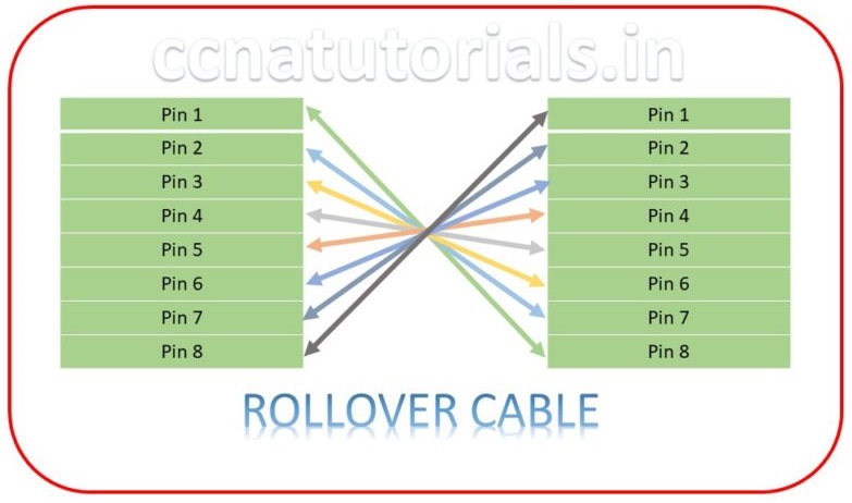
We can say a rollover cable provides connectivity a computer terminal with a router’s or switch’s console. When you need to configure a networking device like a router or switch, you need a roll over cable. Generally it is also known as console cable. The connections on both end are not same. At one end RJ45 connector and comport connector at another end of the cable. Generally the wire used for console cable in Ethernet Cabling Types is flat and of blue color. Cross over cable permits a network administrator to configure the router or switch of the network. The configuration may be troubleshooting, upgrading and maintenance of the networking devices.
Optic Fibre cable in Ethernet Cabling Types
Optic Fibre cable is itself a big chapter to discuss. In this section of Ethernet Cabling Types article, we will take an overview of optic fibre cable. OFC is use to provide connectivity for long distance communication. When we need to connect to LAN of far distance. OFC is the best option to use for connectivity. The OFC allows a very fast and correct data transmission. OFC made of glass and transmit the light through it which carrying the information. It provides the point to point communication. Optic fiber cable is a transmission media which carry information from source to destination in the form of light. Optic fiber cable interface provides high performance data transfer with high speed.
In Ethernet Cabling Types the OFC is mostly used in telecommunication service like internet, cable tv etc. In most case the Optic Fiber Cable replaced the copper cable connectivity. Maximum companies shifts to OFC from other transmission media. The best example of OFC is google fiber services which provides Gbps speed of internet to user.
The Interface of OFC cable in Ethernet Cabling Types
The data transfer from a source to destination in the form of laser light beam. The light is not continues but in the pulse according to the digital signal. We can say the light pulse are the binary bits which are on and off condition.
Since there is no any electromagnetic wave transmission in the optic fiber cable so the interference is 0. In metal wire the signal transmitted in the form of electromagnetic wave so there are always interference occurs. This is the big reason to adopt OFC in place of copper wire communication system.
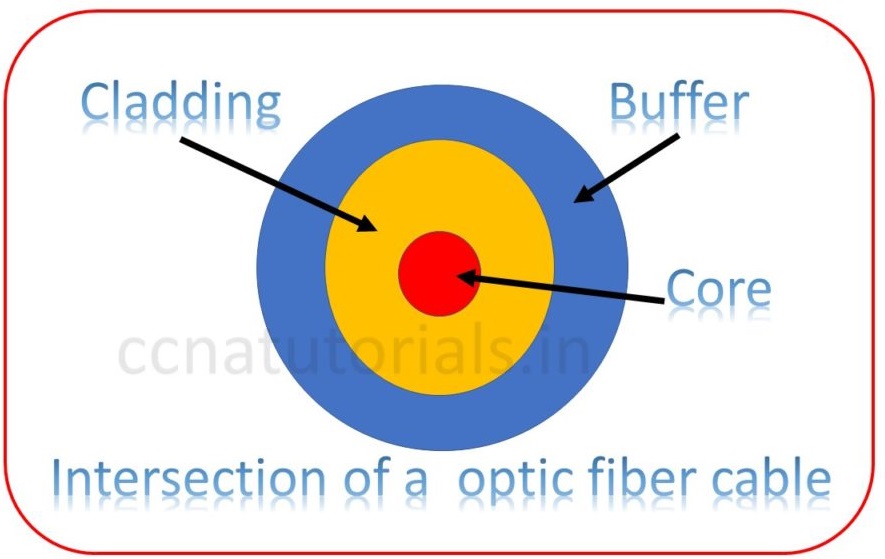
Optic Fiber Cable invented in the decade of 1970’s. The Optic Fiber Cable made of hard outer layer of plastic known as jacket, a transparent core surrounded by cladding with a lower index of refraction.
Single Mode Optic fiber Cable in Ethernet Cabling Types
Single mode optic fiber cable contains two fibers in a single OFC cable. One fiber is for transmission and other is for reception the signal. Single mode fiber cable used when multiple channels transmitted on a single carrier after multiplexing. Multiplexing is generally wave division multiplexing. Single mode optic fiber provides the transmission rate 50 times than the multi-mode optic fiber. The small core and single light wave transmitted distortion free from one end to another end. The difference between the refractive index of core and cladding is very small. Only single type light ray can travel through it.
Multi Mode Optic Fiber Cable in Ethernet Cabling Types
Multi mode optic fiber cable contains multiple core in the cable. The Multi mode optic fiber cables are used for short distance multiple communication. Generally multi-mode optic fiber cable carry multiple light signal so the chances of distortion more than the single mode optic fiber cable. The refractive index of core and cladding is very different.
Step Index Optical Fiber cable in Ethernet Cabling Types
The refractive index of the core and cladding remains constant in the step index optical fiber cable. The light ray propagate through it in the form of meridional ray.
Graded Index Optical fiber cable in Ethernet Cabling Types
The refractive index of core is not uniform. It decreases from the center towards the boundary of core and cladding. The cladding has a uniform refractive index. The rays propagate in the form of skew rays.
Advantages of Optic Fiber Cable compare to other Ethernet Cabling Types
The data transmission speed of OFC is very fast then copper wires. OFC can carry much more band width than the copper wire. The loss of data in OFC is very low than the copper wire. The attenuation of Optic Fiber Cable is very low. There is no any electromagnetic interference effect on the OFC. It is very difficult to tap the OFC for data theft. The life of optic fiber cable is approx 40 years which is much more than the copper wires. Along with these advantages there are some disadvantages of Optic Fiber Cable.
Disadvantages of Optic Fiber cable compare to other Ethernet Cabling Types
The installation and maintenance of OFC is difficult then the copper wire. Very high configuration machines required to handle the OFC. The cost of installation of Optic Fiber Cable communication is much more than the copper wire. The propagation of light is one side so we need separate OFC for transmit and receive the data.
In this article I describe the Ethernet Cabling Types with Ethernet basic concepts which includes the collision and broadcast domain, frame format and IEEE standards. I hope you found this article helpful. For any query or suggestion you may drop a comment below or contact us. Your suggestions are always welcome by us.


I like this site so much, saved to favorites. “American soldiers must be turned into lambs and eating them is tolerated.” by Muammar Qaddafi.