Contents of this article
In this article I describe the term IP routing in router related to networking. IP routing in router is a process of packet transfer between different networks via a router. When we access the internet or intranet the data packets transmitted and received by IP routing in router. Every interface of router has a different network. Routers are also known as layer3 device. Various routing and routed protocols used for moving packets between different networks. Generally the IP routing in router is done by static routing, default routing and dynamic routing protocols. In this article I brief all the three terms with configuration commands.
Requirement of IP routing in router
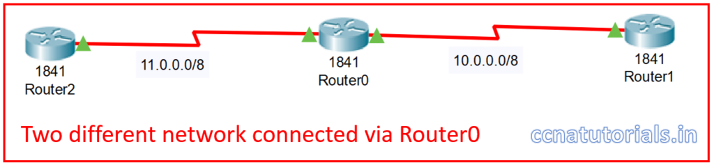
The function of a router is to move the data packets from one interface to another interface or we can say between different networks. The movement of packets done at layer 3 which is known as network layer of the OSI reference model. Router keep the information of neighbour router and network in its routing table. There may be many interfaces in a router which connect different networks.
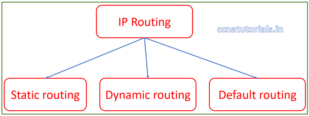
How the router moves the packet to its destination it depends on routing and routed protocol. IP routing in router are set of protocols which allow the router to transfer the packet to its destination. To understand the IP routing in router it is necessary to know about the routing and routed protocol firstly. IP routing are of three types static routing, dynamic routing and default routing.
Routing protocol for IP Routing in router
Routing protocols helps router to build and maintain the routing table in routers. Routing protocols are one important part of IP routing in router. Routing protocols inform the router about the networks connected at each interface. Routing protocols doesn’t carry or push the data packets in any way. Any change in the network required to be update in the routing tables of all routers. This task is carried out by the routing protocols. Routing protocols help the routers to select the best path to exit the data packets. Example of routing protocols are RIP, RIPv2, IGRP,OSPF etc.

Routing protocols further divided into distance vector, link state and hybrid protocols. These all routing protocols update the routing table of all routers in the network. You can see the routing protocols by “show ip route” command in privilege command mode of router. Routing protocols are not responsible for data packet flow in any way. Routing protocols spread the information of network hierarchy to all routers.
Routed protocol for IP Routing in router
Routed protocol works with the data packets for IP routing in router. Routed protocol sends the data packets within a router’s interfaces. Routing protocol decide the best path and routed protocol send the packets on these paths. Routed protocols are defined on interfaces of router. Routed protocols do not update or maintain the routing table in a router. Routed protocols are responsible for flow of data packets from one network to another network.
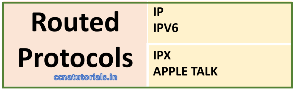
Routed protocols sends the data packets to correct exit interface of the router. Routed protocols are configured on interfaces of the router. Example of routed protocols are IP, IPv6, IPX and Appletalk. Routed protocols are basically addressing schema of the interfaces of router. Router identify the destination network of a data packet and send the data packet to correct exit interface. The concept of subnetting takes place in routed protocols.
Fundamentals of IP routing in router
We know that routers used to connect the different LAN and WAN. We required to connect the different network with a router physically firstly. After completion of physical connectivity next step is to configure the logical network addresses and routing protocols. Each LAN or WAN works in a fix network ID. In case of router I mention the network ID for each LAN. When we work in a LAN, I mention the IP address for each host. Each host assigned a gateway which is the interface of the router to out the packet from that LAN. Router do not forward the packet to host. Router transfer the packet for network ID.
The flow of packets between different LAN depends on destination address on the packet. All routers maintain the routing table to determine the best route to remote network. Routing protocol keep update the routing table in IOS of router. The routing table help to find the destination network of a packet. Basically multiple protocols works for IP routing in router to transfer the data between different networks.
Commands to check the routing table
We can see the routing table in privilege command mode of router. “show ip route” command can be use to check the routing table in a router. see the below command which show the routing table of the router.
 Router>
 Router>en
 Router#show ip rou
 Router#show ip route
 Codes: C - connected, S - static, I - IGRP, R - RIP, M - mobile, B - BGP
 D - EIGRP, EX - EIGRP external, O - OSPF, IA - OSPF inter area
 N1 - OSPF NSSA external type 1, N2 - OSPF NSSA external type 2
 E1 - OSPF external type 1, E2 - OSPF external type 2, E - EGP
 i - IS-IS, L1 - IS-IS level-1, L2 - IS-IS level-2, ia - IS-IS inter area
 * - candidate default, U - per-user static route, o - ODR
 P - periodic downloaded static route

 Gateway of last resort is not set

 C 2.0.0.0/8 is directly connected, Loopback0
 C 10.0.0.0/8 is directly connected, Serial0/0/0
 C 11.0.0.0/8 is directly connected, Serial0/0/1
 192.165.23.0/32 is subnetted, 1 subnets
 O 192.165.23.1 [110/65] via 10.0.0.1, 00:00:02, Serial0/0/0
 192.168.25.0/32 is subnetted, 1 subnets
 O 192.168.25.1 [110/65] via 10.0.0.1, 00:00:02, Serial0/0/0
 192.168.30.0/32 is subnetted, 1 subnets
 O 192.168.30.1 [110/65] via 10.0.0.1, 00:00:02, Serial0/0/0

 Router#
Static Route for IP routing in router
Static route configured manually for IP routing in router. Static route used to transfer the data packet to right next hope with IP routing in router, so the data packet can be sent to its destination network segment. The Static route used in small networks. Router communicate with the next connected network device automatically. Router can not save the network ID beyond the next router.
Network administrator manually configured the network ID beyond the next router in routing table. Static route are not advertise routing table automatically for IP routing in router. If there is any change occurs in the network, network administrator needs to do changes in routing table manually. In complex or large network static routing in a router is very critical so dynamic routing use in router.
Purpose of Static route for IP routing in router
Static route in a router describe the exit interface for a data packet. Static route in router is very efficient in small networks because the engagement time for broadcasting the routing table is not available.
Configuration of static route for IP Routing in router
We created a small network with two routers for configuration of static route for IP routing in router as shown in picture below. There are three different networks with network ID 10.0.0.0/8, 192.168.1.1/24 and 10.10.10.0/24. We configure the static routes in both routers so network 10.0.0.0/8 and 10.10.10.0/24 can communicate with each other.
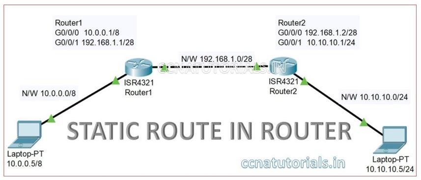
Configure the PC1 IP address 10.0.0.5/8 and gateway 10.0.0.1 similarly the PC2 IP address 10.10.10.5/24 and gateway 10.10.10.1.
Configuring the IP address of Router 1 interfaces
We need to enter in Global configuration mode to set the IP address of interfaces in any router. The interface Gigabitethernet0/0/0 relates to PC1 and require the IP address 10.0.0.1/8. The interface Gigabitethernet0/0/1 relates to Router 2 and require the IP address 192.168.1.1/28. Following commands are used for setup the IP address on both interfaces.
Router1>enable
Router1#
Router1#configure terminal Enter configuration commands, one per line. End with CNTL/Z.
Router1(config)#interface GigabitEthernet0/0/0 Router1(config-if)#ip address 10.0.0.1 255.0.0.0 Router1(config-if)#no shutdown Router1(config-if)#

%LINK-5-CHANGED: Interface GigabitEthernet0/0/0, changed state to up

%LINEPROTO-5-UPDOWN: Line protocol on Interface GigabitEthernet0/0/0, changed state to up

Router1(config-if)#exit
Router1(config)#interface GigabitEthernet0/0/1 Router1(config-if)#ip address 192.168.1.1 255.255.255.240 Router1(config-if)#no shutdown Router1(config-if)#

%LINK-5-CHANGED: Interface GigabitEthernet0/0/1, changed state to up

%LINEPROTO-5-UPDOWN: Line protocol on Interface GigabitEthernet0/0/1, changed state to up
Configuring the IP address of Router 2 interfaces
We need to enter in Global configuration mode to set the IP address of interfaces in any router. The interface Gigabitethernet0/0/0 relates to Router1 and require the IP address 192.168.1.2/28. The interface Gigabitethernet0/0/1 relates to PC2 and require the IP address 10.10.10.1/24. Following commands are used for setup the IP address on both interfaces
Router2>enable
Router2#
Router2#configure terminal Enter configuration commands, one per line. End with CNTL/Z.
Router2(config)#interface GigabitEthernet0/0/0 Router2(config-if)#ip address 192.168.1.2 255.255.255.240 Router2(config-if)#no shutdown Router2(config-if)#

%LINK-5-CHANGED: Interface GigabitEthernet0/0/0, changed state to up

%LINEPROTO-5-UPDOWN: Line protocol on Interface GigabitEthernet0/0/0, changed state to up

Router2(config-if)#exit
Router2(config)#interface GigabitEthernet0/0/1 Router2(config-if)#ip address 10.10.10.1 255.255.255.0 Router2(config-if)#no shutdown Router2(config-if)#

%LINK-5-CHANGED: Interface GigabitEthernet0/0/1, changed state to up

%LINEPROTO-5-UPDOWN: Line protocol on Interface GigabitEthernet0/0/1, changed state to up
After configuring both router’s interface try to ping the PC1 with PC2. You can see that PC1 is not pinging PC2. See the result below
C:\>ping 10.10.10.5

Pinging 10.10.10.5 with 32 bytes of data:

Request timed out.
Request timed out.
Request timed out.
Request timed out.

Ping statistics for 10.10.10.5:
    Packets: Sent = 4, Received = 0, Lost = 4 (100% loss),
Routing in both routers required to communicate PC1 with PC2. Now we configure the static route in both routers 1 and 2 for IP routing in router. A router itself identify the next hope IP address. For example, here router 2 connected with Gigabitethernet0/0/1 interface of router1. Router1 identify the IP address of router2 interface which is connected with it. Similarly, router 2 identify the ip address of router1 interface. The formula for static router is following

Configuration of static route in router 1
Router 1 identify the two networks connected with it are 10.0.0.0/8 and 192.168.1.0/28. Router 1 do not know about the network 10.10.10.0/24. By configuring static route in router1, we set the path of packets for destination 10.10.10.0/24. Run below commands to set the static route in router1.
Router1>enable
Router1#
Router1#configure terminal Enter configuration commands, one per line. End with CNTL/Z.
Router1(config)#ip route 10.10.10.0 255.255.255.0 192.168.1.2 Router1(config)#
Check the static routing in router 1 by running following command. In the result you can see the static route 10.10.10.0/24 via 192.168.1.2. other directly connected network also shown in the result of “show ip route” command
Router1>
Router1>en
Router1#show ip route
Codes: L - local, C - connected, S - static,
R - RIP, M - mobile, B - BGP
D - EIGRP, EX - EIGRP external,
O - OSPF, IA - OSPF inter area
N1 - OSPF NSSA external type 1,
N2 - OSPF NSSA external type 2
E1 - OSPF external type 1,
E2 - OSPF external type 2, E - EGP
i - IS-IS, L1 - IS-IS level-1, L2 - IS-IS level-2, ia - IS-IS inter area
* - candidate default, U - per-user static route, o - ODR
P - periodic downloaded static route

Gateway of last resort is not set

10.0.0.0/8 is variably subnetted, 3 subnets, 3 masks
C 10.0.0.0/8 is directly connected, GigabitEthernet0/0/0
L 10.0.0.1/32 is directly connected, GigabitEthernet0/0/0
S 10.10.10.0/24 [1/0] via 192.168.1.2 192.168.1.0/24 is variably subnetted, 2 subnets, 2 masks
C 192.168.1.0/28 is directly connected, GigabitEthernet0/0/1
L 192.168.1.1/32 is directly connected, GigabitEthernet0/0/1
Router1#
Configuration of static route in router 2
Router 2 identify the two networks connected with it are 192.168.1.0/28 and 10.10.10.0/24. Router 2 do not know about the network 10.0.0.0/8. By configuring static route in router2, we set the path of packets for destination 10.0.0.0/8. Run below commands to set the static route in router2.
Router2>enable
Router2#
Router2#configure terminal Enter configuration commands, one per line. End with CNTL/Z.
Router2(config)#ip route 10.0.0.0 255.0.0.0 192.168.1.1 Router2(config)#
Check the static routing in router 2 by running command “show ip route” in privilege mode. In the result you can see all directly connected network id and static route for 10.0.0.0/8 via 192.168.1.1.
Router2>en
Router2#show ip route
Codes: L - local, C - connected,
S - static, R - RIP, M - mobile,
B - BGP
D - EIGRP, EX - EIGRP external,
O - OSPF, IA - OSPF inter area
N1 - OSPF NSSA external type 1,
N2 - OSPF NSSA external type 2
E1 - OSPF external type 1,
E2 - OSPF external type 2, E - EGP
i - IS-IS, L1 - IS-IS level-1,
L2 - IS-IS level-2, ia - IS-IS inter area
* - candidate default, U - per-user static route, o - ODR
P - periodic downloaded static route

Gateway of last resort is not set

10.0.0.0/8 is variably subnetted, 3 subnets, 3 masks
S 10.0.0.0/8 [1/0] via 192.168.1.1 C 10.10.10.0/24 is directly connected, GigabitEthernet0/0/1
L 10.10.10.1/32 is directly connected, GigabitEthernet0/0/1
192.168.1.0/24 is variably subnetted, 2 subnets, 2 masks
C 192.168.1.0/28 is directly connected, GigabitEthernet0/0/0
L 192.168.1.2/32 is directly connected, GigabitEthernet0/0/0

Router2#
After configuring the static route in both routers try to ping PC1 with PC2. You will get the result as below.
C:\>ping 10.10.10.5

Pinging 10.10.10.5 with 32 bytes of data:

Reply from 10.10.10.5: bytes=32 time<1ms TTL=126
Reply from 10.10.10.5: bytes=32 time<1ms TTL=126
Reply from 10.10.10.5: bytes=32 time<1ms TTL=126
Reply from 10.10.10.5: bytes=32 time<1ms TTL=126

Ping statistics for 10.10.10.5:
    Packets: Sent = 4, Received = 4, Lost = 0 (0% loss),
Approximate round trip times in milli-seconds:
    Minimum = 0ms, Maximum = 0ms, Average = 0ms
Default Routing for IP routing in router
Default routing is configured manually like static routing for IP routing in router. Default routing allow all packets to forward to fix next hope. Generally in the last router default routing configured because there is only a single exit interface.
Default routing protocol allow all packets to forward on a fix interface. Default routing in router is mostly configured when the router have only one exit interface. In other words we can use the default routing in router when the traffic need to be routed on fix next hope. Default routing used when no other router available for a packet to exit out.
Function of default routing for IP routing in router
After receiving a packet router first check the destination IP address of packet. Router see the routing table for the entry of destination network of packet. If the destination network entry available in routing table the packet forwarded to next hop.
If the routing table doesn’t have any entry for destination network, the packet dropped. Suppose we have a router with only one exit interface available. We want to forward all packets to send to next hope without checking the destination IP address. Default routing supports this condition to forward all packets to next hope. In default routing router forward all data packets to next hop for IP routing in router.
Configuration of default routing for IP routing in router
Default routing describe the fix exit interface for all packets for IP routing in router. We created a small network to understand the configuration of default routing for IP routing in router as shown in picture below. There are three different networks with network ID 10.0.0.0/8, 192.168.1.1/24 and 10.10.10.0/24. We configure the default routes in both routers so network 10.0.0.0/8 and 10.10.10.0/24 can communicate with each other.
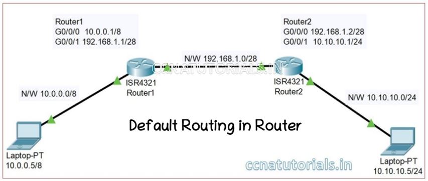
Configure the PC1 IP address 10.0.0.5/8 and gateway 10.0.0.1 similarly the PC2 IP address 10.10.10.5/24 and gateway 10.10.10.1.
Configuring the IP address of Router 1 interfaces
We need to enter in Global configuration mode to set the IP address of interfaces in any router. The interface Gigabitethernet0/0/0 relates to PC1 and require the IP address 10.0.0.1/8. The interface Gigabitethernet0/0/1 relates to Router 2 and require the IP address 192.168.1.1/28. Following commands are used for setup the IP address on both interfaces.
Router1>enable
Router1#
Router1#configure terminal
Enter configuration commands, one per line. End with CNTL/Z.
Router1(config)#interface GigabitEthernet0/0/0
Router1(config-if)#ip address 10.0.0.1 255.0.0.0
Router1(config-if)#no shutdown
Router1(config-if)#

%LINK-5-CHANGED: Interface GigabitEthernet0/0/0, changed state to up

%LINEPROTO-5-UPDOWN: Line protocol on Interface GigabitEthernet0/0/0, changed state to up

Router1(config-if)#exit
Router1(config)#interface GigabitEthernet0/0/1
Router1(config-if)#ip address 192.168.1.1 255.255.255.240
Router1(config-if)#no shutdown
Router1(config-if)#

%LINK-5-CHANGED: Interface GigabitEthernet0/0/1, changed state to up

%LINEPROTO-5-UPDOWN: Line protocol on Interface GigabitEthernet0/0/1, changed state to up
Configuring the IP address of Router 2 interfaces
We need to enter in Global configuration mode to set the IP address of interfaces in any router. The interface Gigabitethernet0/0/0 relates to Router1 and require the IP address 192.168.1.2/28. The interface Gigabitethernet0/0/1 relates to PC2 and require the IP address 10.10.10.1/24. Following commands are used for setup the IP address on both interfaces.
Router2>enable
Router2#
Router2#configure terminal
Enter configuration commands, one per line. End with CNTL/Z.
Router2(config)#interface GigabitEthernet0/0/0
Router2(config-if)#ip address 192.168.1.2 255.255.255.240
Router2(config-if)#no shutdown
Router2(config-if)#

%LINK-5-CHANGED: Interface GigabitEthernet0/0/0, changed state to up

%LINEPROTO-5-UPDOWN: Line protocol on Interface GigabitEthernet0/0/0, changed state to up

Router2(config-if)#exit
Router2(config)#interface GigabitEthernet0/0/1
Router2(config-if)#ip address 10.10.10.1 255.255.255.0
Router2(config-if)#no shutdown
Router2(config-if)#

%LINK-5-CHANGED: Interface GigabitEthernet0/0/1, changed state to up

%LINEPROTO-5-UPDOWN: Line protocol on Interface GigabitEthernet0/0/1, changed state to up
After configuring both router’s interface try to ping the PC1 with PC2. You can see that PC1 is not pinging PC2. See the result below
C:\>ping 10.10.10.5

Pinging 10.10.10.5 with 32 bytes of data:

Request timed out.
Request timed out.
Request timed out.
Request timed out.

Ping statistics for 10.10.10.5:
    Packets: Sent = 4, Received = 0, Lost = 4 (100% loss),
Routing in both routers required to communicate PC1 with PC2. Now we configure the default route in both routers 1 and 2. A router itself identify the next hope IP address. For example, here router 2 connected with Gigabitethernet0/0/1 interface of router1. Router1 identify the IP address of router2 interface which is connected with it. Similarly, router 2 identify the ip address of router1 interface. The formula for default routing is following

Configuration of default route in router 1
Router 1 identify the two networks connected with it are 10.0.0.0/8 and 192.168.1.0/28. Router 1 do not know about the network 10.10.10.0/24. By configuring default route in router1, we set the path of all packets to forward on next hope 192.168.1.2 or router 2
Router1>enable
Router1#
Router1#configure terminal
Enter configuration commands, one per line. End with CNTL/Z.
Router1(config)#ip route 0.0.0.0 0.0.0.0 192.168.1.2
Router1(config)#
Check the static routing in router 1 by running following command. In the result you can see the static route 10.10.10.0/24 via 192.168.1.2. other directly connected network also shown in the result of “show ip route” command
Router1#sh ip route
Codes: C - connected, S - static, I - IGRP, R - RIP,
M - mobile, B - BGP
D - EIGRP, EX - EIGRP external,
O - OSPF, IA - OSPF inter area
N1 - OSPF NSSA external type 1,
N2 - OSPF NSSA external type 2
E1 - OSPF external type 1, E2 -
OSPF external type 2, E - EGP
i - IS-IS, L1 - IS-IS level-1,
L2 - IS-IS level-2, ia - IS-IS inter area
* - candidate default, U - per-user static route,
 o - ODR
P - periodic downloaded static route


Gateway of last resort is 192.168.1.2 to network 0.0.0.0

C 10.0.0.0 is directly connected, GigabitEthernet0/0/0
C 192.168.1.0/24 is directly connected, GigabitEthernet0/0/1
You can see the result shown above Gateway of last resort in 192.168.1.2 to network 0.0.0.0 means the default route is set in router 1. In router 2 we configure static route and then check whether both PC communicate with each other or not?
Configuration of static route in route 2
Router 2 identify the two networks connected with it are 192.168.1.0/28 and 10.10.10.0/24. Router 2 do not know about the network 10.0.0.0/8. By configuring static route in router2, we set the path of packets for destination 10.0.0.0/8. Run below commands to set the static route in router2.
Router2>enable
Router2#
Router2#configure terminal
Enter configuration commands, one per line. End with CNTL/Z.
Router2(config)#ip route 10.0.0.0 255.0.0.0 192.168.1.1
Router2(config)#
Check the static routing in router 2 by running command show ip router in privilege mode. In the result you can see all directly connected network id and static route for 10.0.0.0/8 via 192.168.1.1. see the result below
Router2>en
Router2#show ip route
Codes: L - local, C - connected, S - static, R - RIP,
M - mobile, B - BGP
D - EIGRP, EX - EIGRP external, O - OSPF,
IA - OSPF inter area
N1 - OSPF NSSA external type 1,
N2 - OSPF NSSA external type 2
E1 - OSPF external type 1,
E2 - OSPF external type 2, E - EGP
i - IS-IS, L1 - IS-IS level-1,
L2 - IS-IS level-2, ia - IS-IS inter area
* - candidate default, U - per-user static route,
o - ODR
P - periodic downloaded static route

Gateway of last resort is not set
10.0.0.0/8 is variably subnetted, 3 subnets, 3 masks
S 10.0.0.0/8 [1/0] via 192.168.1.1
C 10.10.10.0/24 is directly connected, GigabitEthernet0/0/1
L 10.10.10.1/32 is directly connected, GigabitEthernet0/0/1
192.168.1.0/24 is variably subnetted, 2 subnets, 2 masks
C 192.168.1.0/28 is directly connected, GigabitEthernet0/0/0
L 192.168.1.2/32 is directly connected, GigabitEthernet0/0/0

Router2#
you can see in above result the gateway of last resort is not set means default route is not set here. After configuring the default route in router 1 and static route in router 2 try to ping PC1 with PC2. You will get the result as below
C:\>ping 10.10.10.5

Pinging 10.10.10.5 with 32 bytes of data:

Reply from 10.10.10.5: bytes=32 time<1ms TTL=126
Reply from 10.10.10.5: bytes=32 time<1ms TTL=126
Reply from 10.10.10.5: bytes=32 time<1ms TTL=126
Reply from 10.10.10.5: bytes=32 time<1ms TTL=126

Ping statistics for 10.10.10.5:
Packets: Sent = 4, Received = 4, Lost = 0 (0% loss),
Approximate round trip times in milli-seconds:
Minimum = 0ms, Maximum = 0ms, Average = 0ms
Dynami Routing for IP Routing in router
Dynamic routing propagate the routing table itself for IP Routing in router. We can configure the IP routing in router manually or dynamically. Static IP Routing in router perform the packets transfer very efficiently in small network. It is very difficult to configure and maintain the static IP Routing in router for large networks. We required an automatic method of routing in routers in large networks. Basically routing is necessary to flow the data packets from one network to another network. We configure the routing table in routers to achieve the aim.
Dynamic IP Routing in router helps to select the path for data packets in network. Routing table of routers updates automatically from one router to other routers in a large network. Routers are self responsible to transmit the new update in routing tables. Dynamic routing protocols dynamically select the network distance and other factors for data flow in a large network.
Dynamic IP routing in router explained
Maintenance of routing table in all routers in a network is very critical job. Dynamic IP Routing in router make it easy to maintain the routing table in all routers in a network. Dynamic routing protocols make it easy to take decision to select the best path for data packets. The routers transmits and receive the routing information in a fix time interval and update the routing table. Any change in network is immediately updated in all routers by sharing information. The drawback of dynamic routing is that more bandwidth consumed than static routing. Dynamic routing make easy to maintain the routers in large network.

When a router gone defective or new router added in network, the dynamic protocols updates the routing table in all routers in network. The routers exchange the network update between each other by broadcasting and multicasting.
Example of Dynamic IP Routing in router
In static routing we configure the route in routers manually. Some dynamic routing protocols help to do the job of static routing in all routers in a large network. RIP (Routing information protocol) OSPF ( Open Shortest Path First) are example of dynamic routing protocol. Dynamic routing protocols are further used two methods for sharing the routing information. Distance-vector and Link-State routing protocols used different technique for sharing route table information.
In this article I described the IP routing in router related to networking exam CCNA. I hope you found this article helpful. for any query or suggestions on this topic you may drop a comment below or contact us. your suggestions are always welcome by us.