In this article I describe the Configure and verify EtherChannel (LACP) for CCNA Exam 200-301. EtherChannel is process to create a single logical link by binding multiple switchports in Cisco switch. The main purpose of EtherChannel is to increase the data flow speed and redundancy in Cisco switch. The benefit of Configure and verify EtherChannel (LACP) is that Communication between switches does not breaks in case of failure of one link. In a large network where multiple switches used for connectivity EtherChannel is very useful facility for redundancy and resiliency.
EtherChannel in Cisco switch developed by Cisco for grouping several switchports into one single logical channel. The switch ports grouped in an EtherChannel in Cisco switch, are treated as a single port. There are two versions of EtherChannel in computer networking PAgP and LACP. The standard version is LACP (Link Aggregation Control Protocol). The Cisco version is PAgP Port Aggregation Protocol. The functionality of both versions is same the difference is only of configuration in both versions. It may be beneficial to know about switching concept alongwith the process to Configure and verify EtherChannel (LACP). Lets discuss some common things about switching in a network.
Function of a switch in network requirement to Configure and verify EtherChannel (LACP)
Layer 2 switch connects two or more different devices within a local area network. Switch works like a relay for data transfer between end devices. When the destination of a data packet is beyond the LAN, the packet forwarded to the gateway router. A Switch is a networking device which works at Data link layer in networking. A Switch receive and transmit the data packets between different end devices. We can say the Layer 2 switching basic concepts are related to receive and transmit the data packets in a network.
Switch inspect the header section of the received packet to check the destination IP address and MAC address then forward accordingly. A switch can connect the computers via Ethernet port, Fast Ethernet port and optic fibre port. Switch works on its operating software which store the MAC address of devices connected with the various interfaces of switch. We need to combine the data flow from multiple switchports into one single link known as EtherChannel. See some more terms related to switching and to Configure and verify EtherChannel (LACP) in switch.
The layer 2 switch are always placed behind the gateway device. Router is generally used as gateway device for all data packets of a network. Layer 2 switch works like a bridge between the multiple devices in a computer network. Switch are used to the basic data packet forwarding function to high end configuration switching. The latest switch are capable to create and works with VLAN in the network. The broadcast domain can break by creating the VLAN in switches. Each port of switch creates it’s own collision domain.
Layer 2 switching basic concepts to Configure and verify EtherChannel (LACP)
layer 2 switching done at data link layer in OSI reference model. Data link layer uses MAC address of devices for data transfer. Layer 2 switch break the collision domain. Each port of the layer 2 switch have its own collision domain. Instead of switch, HUB define all ports in a single collision domain. Hub works on physical layer. You should know about the layered approach in a network for data packet switching. You can read the full article related to OSI reference model here.
Each port have its own collision domain. Layer 2 switch forward frames from one device to another. A router decide to forward or drop the packet on the basis of PUD attached with packet. This PUD have the IP address of source and destination. Layer 2 switch forward the frame on the basis of MAC address header on the frame. Layer 2 switch add MAC address of connected devices to its database itself automatically.
Address learning method of switch
Physical address learning is the one of important task in Layer 2 switching basic concepts. Here physical address means MAC address. Each networking device and endpoint device have it’s own unique MAC address. Layer 2 switch maintain a MAC address table in its IOS operating system. This table contains the MAC address of all connected device with the switch. When a frame received at any port of switch then switch filter the MAC address from the frame. If filtered MAC address is not stored in its MAC database then switch save the MAC address. This process done with each frame received by the switch. When a switch is powered on, its MAC address database remains empty.
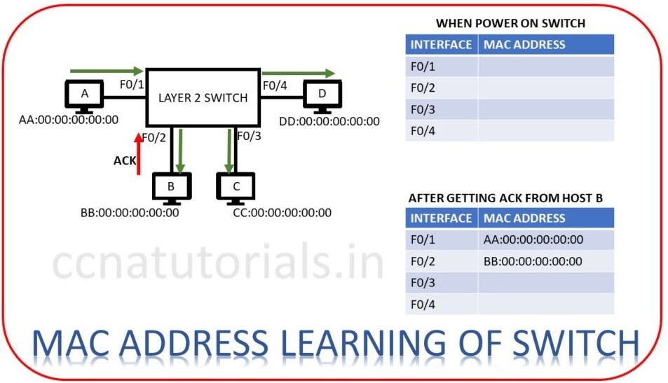
Now let’s device A want to transmit data for device B. Frame encapsulates device A at layer 2. Source address added to each frame transmitted via device A. Switch receive the frame at port F0/1.
As switch boot first time and have no MAC address database. Switch firstly save the MAC address of device A from frame header. Now switch transmit the same frame to each device connected with it except to device A. Device B forward an acknowledgement frame to switch that the frame destination is device B. On getting this acknowledgement switch store the MAC address of device B in its MAC address database table. Next time when device A or B send data to each other, switch forward the frame to correct address according to MAC address table. We can say now device A and B can communicate point to point with each other. Same process done till the MAC address of each connected device stored in its MAC address table.
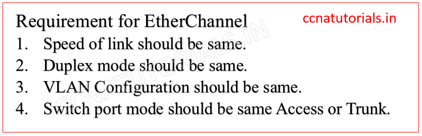
Requirement to Configure and verify EtherChannel (LACP)
I take the scenario shown in below diagram to Configure and verify EtherChannel (LACP). Here we have two switch connected with each other on a 100 mb/s speed. This is because the speed of each switch port is maximum 100 mb/s. The data between both switches can be transfers upto 100 mb/s speed maximum.
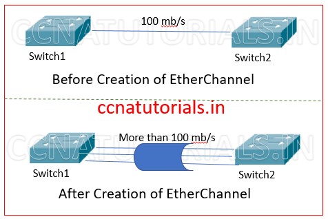
Now we need to transfer the data more than 100 mb/s speed between the switches on a single link. This requirement can be fill by Configure and verify EtherChannel (LACP) by create groups of multiple links. The important thing is that STP will not block the linked ports. Remember what STP done when more than one link established between switches. STP block the ports to avoid creating loops between the switch. Since the logical link created by multiple ports works as single link, STP does not block any link of EtherChannel ports. The single link will provide more than 100 mb/s speed between switches.
Process to Configure and verify EtherChannel (LACP)
LACP link aggregation control protocol defined in 802.3ad. LACP protocol is used to create an EtherChannel between two switches. There are multiple modes which can be set according to our requirement. The ON mode allow the interface to be a part of EtherChannel without any negotiation. The OFF mode remove the EtherChannel from the switchports. In Active mode the ports forcefully became a part of EtherChannel. In Passive mode the port became a part of EtherChannel only when requested from the opposite switch. We Run the below commands in CLI of switch 1 to Configure and verify EtherChannel (LACP).
 Switch1>
 Switch1>en
 Switch1#config t
 Switch1(config)# interface fa0/1
 Switch1(config-if)# channel-group mode active
 Switch1(config)# interface fa0/2
 Switch1(config-if)# channel-group mode active
 Switch1(config)# interface port-channel 1
 Switch1(config-if)# switchport trunk encapsulation dot1q
 Switch1(config-if)# switchport mode trunk
 Switch1(config-if)# do wr
After running above command in CLI of switch1 configure the switch2 by running the below commands.
 Switch2>
 Switch2>en
 Switch2#config t
 Switch2(config)# interface fa0/1
 Switch2(config-if)# channel-group mode active
 Switch2(config)# interface fa0/2
 Switch2(config-if)# channel-group mode active
 Switch2(config)# interface port-channel 1
 Switch2(config-if)# switchport trunk encapsulation dot1q
 Switch2(config-if)# switchport mode trunk
 Switch2(config-if)# do wr
Configure and verify EtherChannel (PAgP)
Port Aggregation Protocol (PAgP) is a Cisco proprietary protocol. PAgP protocol is used to form the EtherChannel in Cisco switch. There are different modes for PAgP protocol EtherChannel. The modes are ON, Desirable, Auto and off. On mode allow a port to be a part of EtherChannel. Desirable mode allow a port to be a part of EtherChannel permanently. Auto mode allow a port to be a part of EtherChannel when required by opposite side switch. OFF mode remove the port from the EtherChannel. So to configure the PAgP run the below commands in CLI of switch1.
 Switch1>
 Switch1>en
 Switch1#config t
 Switch1(config)# interface fa0/1
 Switch1(config-if)# channel-group 1 mode desirable
 Switch1(config)# interface fa0/2
 Switch1(config-if)# channel-group 1 mode desirable
 Switch1(config)# interface port-channel 1
 Switch1(config-if)# switchport trunk encapsulation dot1q
 Switch1(config-if)# switchport mode trunk
I hope you found this article helpful related to Configure and verify EtherChannel (LACP). For any query or suggestion on this article you may contact us or drop a comment in the below comment form. Your suggestions are always welcome by us.