Contents of this article
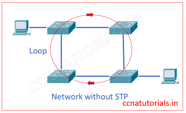
In This article I explain the Spanning Tree protocol STP. Spanning Tree Protocol STP provide the loop avoidance in a network, where multiple switches are connected with each other as shown in below image. The Spanning Tree Protocol STP is layer 2 protocol of OSI reference model. STP automatically shut down the redundant links which creates the loops. The redundant link creates a loop between switches. STP monitors all links of the network. Spanning Tree Protocol STP finds the redundant link by the Spanning Tree Algorithm. The STA algorithm creates a topology database to find the redundant links.
Function of Spanning Tree Protocol STP
To explain the function of STP I select the network as shown in below image. There are four switch connected with each other. It is possible the loop may automatically create between switches. This loop is vulnerable to the network. You can assume the result of such loops.
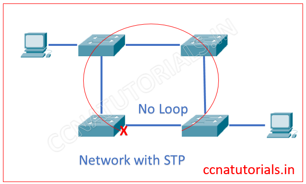
We configured STP in a switch. The STP finds the redundant link which creates loop and disable it. The below image explain itself the STP.
Common terms of Spanning Tree Protocol STP
Root Bridge and Bridge ID
The Root Bridge is a switch which have lowest bridge priority ID. The Root Bridge switch is the main focus point for all switches in the network. Root Bridge is the main switch of the network. In case the bridge priority value is same in all network switches, the lowest MAC ID use to select the root bridge. In Cisco switches the default bridge ID remains 32768. This Bridge Id can be manually changed. So if you want to make a particular switch root bridge, you need to change its bridge id. Every time when network topology changed the root bridge may be changed. I mean when a new switch added to network or any existing switch removed from the network. In case of failure of Root Bridge, remaining switches automatically select the next root bridge.
Non Root Bridges
All bridges except the root bridge are known as Non Root Bridge. Non Root Bridges communicate with root bridges and keep update the STP topology database.
BPDU Bridge Protocol Data Unit
BPDU are multicast frame which transmitted between the switches. BPDU contains the information of all connections and link of a switch. BPDU also contains the Bridge ID of a Bridge.
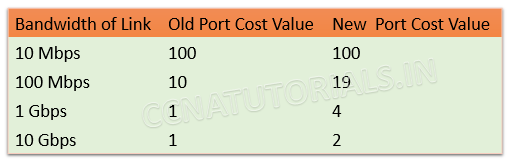
Port Cost
Port Cost is defined by the data transfer speed or bandwidth of a link. The Port cost is the main factor to determine the best path among the multiple links. Below image show the port cost of Cisco switches.
Path Cost
Path cost is dependent value of port cost. It is always counted from the root bridge. When BPDU broadcast from the root bridge the Path cost remains 0. Each switch received the BPDU add 1 to the path cost. So we can say if there are two switch in a path from Root Bridge to a switch the path cost will be 4 for that switch.
Root Port
The root port is the link with lowest path cost. In other words we can say the directly connected link with the root bridge is known as root port. In case more than one links connected with the root bridge bandwidth of each link define the lowest cost port and become the root port.
Designated Port
Designate port is the port which have lowest cost to the network segment compared to other ports on that network segment. Designated port also known as forwarding port. A network segment can have only one forwarding or designated port.
Non Designated port
All ports having higher cost than the designated port known as non-designated port. These are not forwarding ports.
Forwarding port
A root port or designated port forwards frames and known as forwarding ports.
Blocked Port
A blocked port prevents the loops by blocking the frame forwarding. A blocked port do not transmit any frame in the network.
Backup Port
Backup port is a port on same network segment as on designated port.
Spanning Tree Protocol STP Disable state
In disable state the port do not forward or receive any frame. We can say the port remain in idle state or not operational.
Spanning Tree Protocol STP Blocking state
When you power on a switch, all ports remain in blocking state. A block port does not forward any frames in the network. A blocked port only listen to the BPDUs. Blocking state prevent the loops in the network.
Spanning Tree Protocol STP Listening state
In listening state the ports received the BPDUs. Listening ports make sure no loops occurs in the network. Listening ports forward the data frames without advertise the mac address table.
Spanning Tree Protocol STP Learning state
In learning state the ports still listen the BPDUs. Only root and designated ports go into the learning state. In learning state switch see the source address of frame and update the MAC table. Learning state time is 15 seconds only.
Spanning Tree Protocol STP Forwarding state
In forwarding state the port receive and forward the data frames. Switch forwarded the MAC address in forwarding state. This state take place after completion of convergence.
I hope you found this article helpful related to spanning tree protocol STP. For any query or suggestion on this article you may contact us or drop a comment below. Your suggestions are always welcome by us.

Rattling great information can be found on website. “Often the test of courage is not to die but to live.” by Conte Vittorio Alfieri.