In this article i explain the inter VLAN routing configuration in Cisco router. We know the functionality of VLAN in a network. All devices of same VLAN can communication with each other. The feature of inter VLAN communication is not available. We can transfer the data packets between same VLAN in different switches with the help of trunk port access.
VLAN provides multiple virtual networks in a physical network. We can break a local area network into multiple virtual networks. The devices of same virtual network can communicate with each other without interfere to other virtual network. The switchports of a switch can be used as access port or trunk port. The function of access port and trunk port are different.
The switch provide a single broadcast domain to all connected devices by default. Each port of switch creates single collision domain. VLAN breaks the broadcast domain into small broadcast domain. If we need to make communication between different VLANs then we need a router. Router have the feature to provide communication between different networks. VLAN provides the logical network within a single physical network.
VLAN basic concepts
Every switchport works on separate collision domain. We can say each device connected with a switchport remains in separate collision domain. By default all switchports of a switch works in a single broadcast domain. It can be define as all the devices working in a single LAN remains in a single broadcast domain. The big network of single broadcast domain can be divided into different small broadcast domains by creating the VLANs in the network. Every VLAN have its own broadcast domain.
Breaking the large broadcast domain into small broadcast domains provides an extra layer of security in the network. The devices of different broadcast domains can not communicate with each other. The swithports can be configured to restrict the unauthorised use by unwanted devices. Management of networking devices become easier by creating VLANs. Network administrator can monitor the small network more efficiently than a large network.
Methods of adding devices in VLAN
The devices can be added in a VLAN by two methods static and dynamic. Actually we configure the switchports for access by device with these methods. Generally static method assigned to the VLANs as it is easy and secure method. In static method we add the switchports manually to a VLAN. Suppose I assign the switchport number 4 to VLAN 10. This switchport remains assigned to VLAN unless we manually change it or assign to another VLAN. By default all switchports assigned to a single VLAN. We need to assign each port manually to the required VLAN.
The other method is dynamic assignment of swithports to VLAN according to the IP address of a device or MAC address of the device. Suppose a device connected to switchport 2 and it belongs to VLAN 20. If you change the switchport of this device from 2 to 10 then the switchport 10 automatically assigned to VLAN 20 and the device will work as it was. Dynamic method works in high end switches, in normal switch we can use static methods only.
Access port and Trunk port for VLAN basic concepts
Access ports allow a device to access the network by using the NIC or RJ45 connection. The devices connected to access ports remains in same broadcast domain. The device can access, receive and transmit the data via access port. Generally all switchports remains as access ports until we manually convert them to trunk ports.
Trunk port mode allow to transmit and receive the data of multiple VLANs. Generally endpoint devices not connected with trunk ports. The networking devices uses trunk ports to connect with each other. For example when we need to connect two switches which have multiple VLANs, the switches can be connected via trunk ports. The assignment of access ports and trunk ports are logical. A switchport mode can be changed by using the command line interface.
Inter VLAN Routing configuration
In previous article I explained VLAN to VLAN access in trunk mode. To provide communication clients of different VLANs, we need a Router. The process of data transfer between different VLAN is known as Inter VLAN routing. In this article I explain the Inter VLAN routing configuration in Cisco router.
Requirement of Inter VLAN Routing configuration in cisco router.
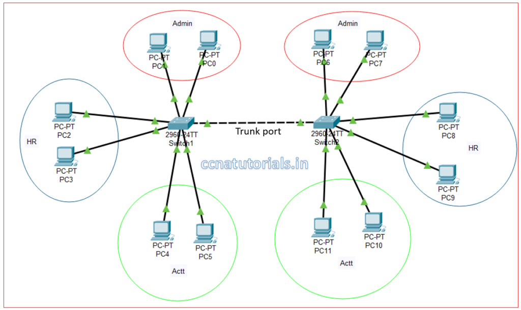
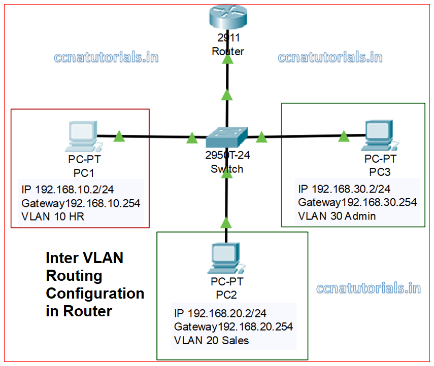
You can see above image the different VLANs in different switches which are connected with each other. The connectivity provided by trunk mode port of both switches. Same VLANs created in both switch. The clients of same VLAN in both switch can communicate with each other. Without inter VLAN routing different VLAN can not communicate with each other. We require a Router to connect with trunk port of switch and do some configuration in router. The clients of different VLANs can communicate with each other only After inter VLAN routing configuration in cisco router.
Configuration of VLANs in switch
There are three different VLANs configured in switch. Port number 24 configured as trunk port and connected with Router’s Gigabitethernet interface. As shown in below image.
First thing we do the creation of VLANs in switch by running the below commands in switch CLI.
 Switch>enable
 Switch#config t
 Switch(config)#vlan 10
 Switch(config-vlan)#name HR
 Switch(config-vlan)#vlan 20
 Switch(config-vlan)#name Sales
 Switch(config-vlan)#vlan 30
 Switch(config-vlan)#name Admin
 Switch(config-vlan)#exit
 Switch(config)#exit
 Switch#
 Switch#show vlan

 VLAN Name Status Ports
 ---- -------------------------------- --------- -------------------------------
 1 default active Fa0/1, Fa0/2, Fa0/3, Fa0/4
 Fa0/5, Fa0/6, Fa0/7, Fa0/8
 Fa0/9, Fa0/10, Fa0/11, Fa0/12
 Fa0/13, Fa0/14, Fa0/15, Fa0/16
 Fa0/17, Fa0/18, Fa0/19, Fa0/20
 Fa0/21, Fa0/22, Fa0/23, Fa0/24
 Gig0/1, Gig0/2
 10 HR active
 20 Sales active
 30 Admin active
 1002 fddi-default active
 1003 token-ring-default active
 1004 fddinet-default active
 1005 trnet-default active
IP addressing to different clients of VLANs in switch
Connect the PC1 with switchport fa0/1, PC2 with switchport fa0/2 and PC3 with switchport fa0/3. Assign Ip address as shown in above image. Gateway is required to be define in Router so the data packets may be route between different VLANs. I assign the switchports to VLAN as shown in below image.It is not necessary to keep the same network ID in all VLANs.
We assign different IP address scheme to each VLAN of switch. Network Ids 192.168.10.0/24, 192.168.20.0/24 and 192.168.30.0/24 assigned to different VLANs as shown in figure above. Assign the IP address to the clients of different VLANs and try to ping with each other. We can see the clients are not pinging to other VLAN’s clients. So now we require a router for inter VLAN routing configuration.
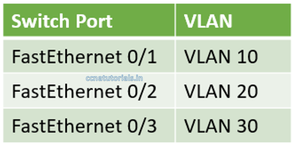
To assign the switchports to VLANs as shown in above image do running the commands as below.
 Switch>enable
 Switch#config t
 Switch(config)#interface fastEthernet 0/1
 Switch(config-if)#switchport access vlan 10
 Switch(config-if)#no shut
 Switch(config)#interface fastEthernet 0/2
 Switch(config-if)#switchport access vlan 20
 Switch(config-if)#no shut
 Switch(config-if)#exit
 Switch(config)#interface fastEthernet 0/3
 Switch(config-if)#switchport access vlan 30
 Switch(config-if)#no shut
 Switch(config-if)#exit
 Switch(config)#do wr
 Building configuration...
 [OK]
 Switch(config)#
 Switch(config)#exit
 Switch#
 Switch#show vlan

 VLAN Name Status Ports
 ---- -------------------------------- --------- -------------------------------
 1 default active Fa0/4, Fa0/5, Fa0/6, Fa0/7
 Fa0/8, Fa0/9, Fa0/10, Fa0/11
 Fa0/12, Fa0/13, Fa0/14, Fa0/15
 Fa0/16, Fa0/17, Fa0/18, Fa0/19
 Fa0/20, Fa0/21, Fa0/22, Fa0/23
 Fa0/24, Gig0/1, Gig0/2
 10 HR active Fa0/1
 20 Sales active Fa0/2
 30 Admin active Fa0/3
 1002 fddi-default active
 1003 token-ring-default active
 1004 fddinet-default active
 1005 trnet-default active
After running above commands, the switchports assigned to related VLANs. Now we require to configure the inter VLAN routing in router
Inter VLAN routing configuration in Router
Router connected with FastEthernet0/24 switchport of switch. We require to assign the gateway for each VLAN of interface of router. We need to configure inter VLAN routing for each VLAN. In this article I show you the inter VLAN configuration of two VLANs only. You can set inter VLAN configuration for multiple VLANs routing. I configure inter VLAN routing for VLAN 10 and VLAN 20 only by running below commands in router.
Configuration of gateway for VLAN 10 HR in router interface
 Router>enable
 Router#config t
 Router(config)#interface gigabitEthernet 0/0
 Router(config-if)#no shut
 Router(config-if)#exit
 Router(config)#interface gigabitEthernet 0/0.10
 Router(config-subif)#encapsulation dot1Q 10
 Router(config-subif)#ip address 192.168.10.254 255.255.255.0
 Router(config-subif)#exit
 Router(config)#do wr
 Building configuration...
 [OK]
 Router(config)#
Configuration of gateway for VLAN 20 Sales in router interface
 Router>enable
 Router#config t
 Router(config)#interface gigabitEthernet 0/0
 Router(config-if)#no shut
 Router(config-if)#exit
 Router(config)#interface gigabitEthernet 0/0.20
 Router(config-subif)#encapsulation dot1Q 20
 Router(config-subif)#ip address 192.168.20.254 255.255.255.0
 Router(config-subif)#exit
 Router(config)#do wr
 Building configuration...
 [OK]
 Router(config)#
After running above commands in router the inter VLAN routing configuration is complete. I configured only for VLAN 10 and 20. Now we require to configure the trunk port in switch.
Configure trunk port in switch for inter VLAN routing configuration.
Router connected with FastEthernet0/24 port with switch. The mode of this port should be trunk. By default, Trunk Port allow to transmit and receive data of all VLANs. It is up to you whether you want to allow the data of all VLANs or for limited VLANs. I show you both configuration for trunk mode.
Change port mode to trunk mode and allow traffic of all VLANs through it. Run the commands below.
 Switch>enable
 Switch#config t
 Switch(config)#interface fastEthernet 0/24
 Switch(config-if)#switchport mode trunk
 Switch(config-if)#do wr
 Building configuration...
 [OK]
 Switch(config-if)#exit
 Switch(config)#
After running above commands, the trunk port transmit and receive the data of all VLANs. We can allow some VLANs to transmit and receive data via trunk port. You can allow only VLAN 10 and 20 to transmit and receive data via trunk port by running the following commands in switch.
 Switch>enable
 Switch#config t
 Switch(config)#interface fastEthernet 0/24
 Switch(config-if)#switchport mode trunk
 Switch(config-if)#switchport trunk allowed vlan 10,20
 Switch(config-if)#do wr
 Building configuration...
 [OK]
 Switch(config-if)#exit
 Switch(config)#
Testing of Inter VLAN routing configuration
After doing the above exercise try to ping the PC1 with PC2. The both PC are communicating with each other.
I hope you enjoy and understood the inter VLAN routing. For any query or suggestion on this article you may contact us or drop a comment below. Your suggestions are always welcome by us.