Contents of this article
In this article, I describe the process of Connecting Two Switches in Packet Tracer to create a LAN. In the ever-evolving landscape of networking, understanding the basics is crucial. One fundamental concept is creating a Local Area Network (LAN), which connects devices within a limited geographical area. In this blog, we’ll explore the process of connecting two switches in packet tracer to establish a simple LAN in Packet Tracer, a versatile network simulation tool developed by Cisco. Let’s embark on our journey to build a network!
The Components required for Connecting Two Switches in Packet Tracer
Before we dive into the configuration process, let’s get familiar with the core components involved in creating our simple LAN by Connecting Two Switches in Packet Tracer:
- Switch: A switch is a networking device that operates at the Data Link Layer (Layer 2) of the OSI model. It’s designed to forward data frames within a LAN based on MAC addresses.
- Packet Tracer: Packet Tracer is a network simulation tool developed by Cisco. It allows users to design, configure, and simulate network topologies, making it an excellent platform for learning and practicing networking concepts.
Now that we’ve identified our key components let’s move on to the step-by-step guide to connecting two switches in Packet Tracer.
Step-by-Step Guide: Creating a Simple LAN with Two Switches
1. Launch Packet Tracer and Create a New Project
To begin, ensure that you have Packet Tracer installed on your computer. Once it’s up and running, follow these steps to create a new project:
- Click on the “File” menu in the top left corner.
- Select “New” to initiate a new project.
- Provide a name for your project and choose a suitable location to save it.
- Click “Create” or “OK” to confirm the project creation.
2. Access the Workspace
After successfully creating a new project, you’ll find yourself in the Packet Tracer workspace—an open canvas ready for your network design.
3. Add Switches to the Workspace
Our LAN will consist of two switches. Here’s how to add them to your workspace:
- On the left-hand side of the Packet Tracer window, you’ll see a panel containing various device categories. Locate the “Switches” category.
- Under “Switches,” select a switch model. For simplicity, let’s start with the “2960” switch.
- Click and drag the selected switch into your workspace. Repeat this process to add a second switch.
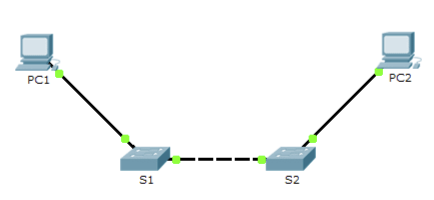
You should now have two switches in your workspace, ready to be connected.
4. Connect the Switches
Now that we have our switches in place, we need to establish a connection between them. Follow these steps:
- In the left-hand sidebar, navigate to the “Connections” category under “Devices.”
- Select the “Copper Straight-Through” cable type. This type of cable is typically used to connect switches and end-user devices within a LAN.
- Click and drag a straight-through Ethernet cable from one switch’s Ethernet port to an Ethernet port on the other switch. As you hover over the switch’s interface, you’ll notice a green indicator. When you hover over the destination interface, you’ll see a red indicator. Connect the cable by clicking on the source interface and then the destination interface.
Congratulations! You’ve successfully physically connected the two switches, creating a link between them.
5. Configure the Switches (Optional)
At this point, your LAN is functional, and devices can communicate across the switches. However, you may want to perform some basic configurations on the switches, such as setting the hostname or enabling specific features. To configure the switches:
- Click on a switch in the workspace to select it.
- At the bottom of the workspace, you’ll find a “CLI” (Command Line Interface) tab. Click on it to access the switch’s command-line interface.
- In the switch’s CLI, you can enter commands to configure various settings. For instance, you can set the hostname using the following command:
  configure terminal
  hostname <switch-name>
Replace <switch-name> with your desired hostname.
- Additionally, you can configure VLANs, spanning tree protocols, or any other advanced settings depending on your specific network requirements.
6. Save Your Project
Before concluding your network configuration, remember to save your Packet Tracer project to retain your network topology and any configurations you’ve made. To save your project:
- Click on “File” in the top menu.
- Select “Save” or “Save As” and choose a suitable name and location for your project.
By following these steps, you’ve successfully connected two switches in Packet Tracer, creating a simple LAN. Devices connected to these switches can now communicate within the same network segment. This basic setup serves as a foundation for more complex network configurations and scenarios as you delve deeper into the world of networking. Packet Tracer provides an excellent platform for learning and practicing various networking concepts, and connecting switches is just one of the many skills you can develop using this versatile tool.
I hope you found this article helpful. You may drop a comment below or contact us for any query about the contents of this website.