Contents of this article
In this article, I describe the process of Connecting a PC to a switch in Packet Tracer. Connecting a PC to a switch in Packet Tracer is a fundamental networking task that forms the basis of building a local area network (LAN) within the simulation environment. Packet Tracer is a network simulation tool developed by Cisco, widely used for educational and training purposes. This guide will walk you through the process of connecting a PC to a switch in Packet Tracer in detail, step by step.
Understanding the Basics:
Before we dive into the process itself, let’s briefly understand the key components and concepts involved:
- Packet Tracer: Packet Tracer is a network simulation tool developed by Cisco that allows users to create, configure, and simulate network environments. It’s commonly used for learning and practicing networking concepts and configurations.
- PC (Personal Computer): In Packet Tracer, a PC typically represents an end-user device, such as a desktop or laptop computer. PCs are used to access and communicate within the network.
- Switch: A switch is a network device that operates at Layer 2 (Data Link Layer) of the OSI model. It’s used to connect multiple devices within a LAN, and it makes forwarding decisions based on MAC (Media Access Control) addresses.
Now, let’s go through the step-by-step process of connecting a PC to a switch in Packet Tracer:
Step 1: Launch Packet Tracer
Ensure you have Packet Tracer installed on your computer. If not, you can download it from the Cisco Networking Academy or Cisco’s official website. Once installed, launch Packet Tracer.
Step 2: Create a New Project
Packet Tracer allows you to work on multiple projects. To create a new project, follow these steps:
- Click on “File” in the top menu.
- Select “New” to create a new project.
- Provide a name for your project, and choose a location to save it.
- Click “Create” or “OK” to confirm the project creation.
Step 3: Access the Workspace
After creating a new project, you’ll be presented with a blank workspace where you can design your network topology.
Step 4: Add Devices to the Workspace
In this step, we’ll add the PC and the switch to our network topology. Here’s how to do it:
- On the left-hand side of the Packet Tracer window, you’ll find a panel with various device categories. Look for the “End Devices” category.
- Under “End Devices,” you’ll see “Laptops.” These laptops represent PCs in the simulation. Click and drag a laptop into the workspace.
- Next, navigate back to the left-hand panel and find the “Switches” category. Click and drag a switch into the workspace.
You should now have a PC (laptop) and a switch in your workspace.
Step 5: Configure the PC
Before connecting the PC to the switch, you need to configure its network settings. To configure the PC, follow these steps:
- Click on the laptop icon in the workspace to select it.
- In the “Physical” tab on the right-hand side, you’ll find the PC’s configuration options.
- Set the following parameters as needed:
- Name: Assign a name to the PC (e.g., PC1).
- IP Configuration: Set the IP address, subnet mask, and default gateway based on your network requirements. Make sure the IP settings are compatible with the network you’re creating.
- DNS Configuration: You can specify DNS servers if necessary.
- Services: These settings can be left at their default values for basic connectivity.
- After configuring the PC, you can close the configuration panel by clicking the “X” icon in the top-right corner.
Step 6: Configure the Switch
Similarly, before connecting devices to the switch, you should configure it. Although basic configurations are often not necessary for simple connections, it’s a good practice to set the switch’s hostname and enable the console password. Here’s how to do it:
- Click on the switch icon in the workspace to select it.
- At the bottom of the Packet Tracer window, you’ll see a tab called “CLI” (Command Line Interface). Click on this tab to access the switch’s command-line interface.
- In the CLI, you can configure various settings. For a basic setup, you can use the following commands:
  enable
  configure terminal
  hostname <switch-name>
  enable secret <password>
  end
  write memory
Replace <switch-name> with your desired hostname and <password> with your chosen enable secret password. The “write memory” command saves your configuration.
Please note that these are basic configurations. More advanced configurations are possible depending on your network requirements.
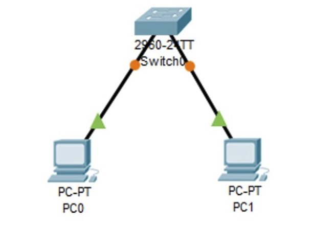
Step 7: Connect the PC to the Switch
Now that both the PC and the switch are configured, you can connect them using an Ethernet cable. In Packet Tracer, you can choose the type of cable you want to use based on your connection needs. In this case, we’ll use a straight-through Ethernet cable:
- On the left-hand side of the Packet Tracer window, find the “Connections” category.
- Under “Connections,” you’ll see various cable types. Look for “Copper Straight-Through.”
- Click and drag a straight-through Ethernet cable from the PC’s Ethernet port to one of the switch’s available ports. When you hover over the PC’s port, you’ll see a green indicator, and when you hover over the switch’s port, you’ll see a red indicator. Connect the cable by clicking on the PC’s port and then the switch’s port.
Step 8: Verify Connectivity
To ensure that your PC is successfully connected to the switch and can communicate within the network, you can perform a few tests:
- Click on the PC (laptop) icon in the workspace to select it.
- At the bottom of the Packet Tracer window, you’ll see a “Desktop” tab. Click on this tab to access the laptop’s desktop.
- On the laptop’s desktop, open a command prompt or terminal window, depending on the operating system emulation.
- Attempt to ping the switch’s IP address to test connectivity. If you haven’t assigned an IP address to the switch, you can try pinging the default gateway you configured for the PC. Use the following command (replace
<gateway-ip>with your actual default gateway IP):
ping <gateway-ip>If the ping is successful, it means the PC is connected to the switch, and basic network connectivity is working.
Step 9: Save Your Project
After successfully connecting the PC to the switch and verifying connectivity, it’s essential to save your project to preserve your network configuration. To save your project, follow these steps:
- Click on “File” in the top menu.
- Select “Save” or “Save As” to save your project with a meaningful name and location of your choice.
Conclusion for Connecting a PC to a switch in Packet Tracer
In conclusion, connecting a PC to a switch in Packet Tracer involves several steps, including creating a new project, adding devices, configuring the PC and switch, physically connecting them with an Ethernet cable, verifying connectivity, and saving your project. This basic setup serves as a foundation for more complex network configurations and allows you to practice essential networking concepts in a simulated environment. As you become more familiar with Packet Tracer, you can explore advanced configurations and build more intricate network topologies for various educational and training purposes. You may drop a comment below or contact us for any query related to the content of this website.