Contents of this article
In this article, I describe the process of Connecting a router to a switch in Packet Tracer. Connecting a router to a switch in Packet Tracer is a fundamental networking task that simulates a common scenario in real-world network setups. This connection allows devices in different network segments to communicate with each other. In this guide, we’ll walk you through the step-by-step process of connecting a router to a switch in Packet Tracer.
The Components required for Connecting a router to a switch in Packet Tracer
Before we dive into the configuration process, let’s familiarize ourselves with the key components involved in this setup:
- Router: A router is a network device that operates at the network layer (Layer 3) of the OSI model. It is responsible for routing data packets between different networks, making decisions based on IP addresses.
- Switch: A switch is a network device that operates at the data link layer (Layer 2) of the OSI model. It uses MAC addresses to forward data frames within a local area network (LAN).
- PCs: Personal computers (PCs) are end-user devices that connect to the switch and router. They communicate with each other through the router and switch.
Step-by-Step Guide for Connecting a router to a switch in Packet Tracer
Now, let’s walk through the process of connecting a router to a switch in Packet Tracer:
1. Launch Packet Tracer and Create a New Project
Ensure that you have Packet Tracer installed on your computer. Once installed, launch the application. To create a new project, follow these steps:
- Click on “File” in the top menu.
- Select “New” to create a new project.
- Provide a name for your project and choose a location to save it.
- Click “Create” or “OK” to confirm the project creation.
2. Access the Workspace
After creating a new project, you’ll be presented with a blank workspace where you can design your network topology.
3. Add Devices to the Workspace
In this step, we’ll add the router, switch, and PCs to our network topology. Here’s how to do it:
- On the left-hand side of the Packet Tracer window, you’ll find a panel with various device categories. Look for the “Routers” category.
- Under “Routers,” select a router model. For simplicity, you can start with a basic router model, such as the “2911” router.
- Click and drag the selected router into the workspace.
- Next, navigate back to the left-hand panel and find the “Switches” category. Click and drag a switch into the workspace.
- Now, add two PCs to the workspace. You can find PCs under the “End Devices” category. Click and drag two PCs into the workspace.
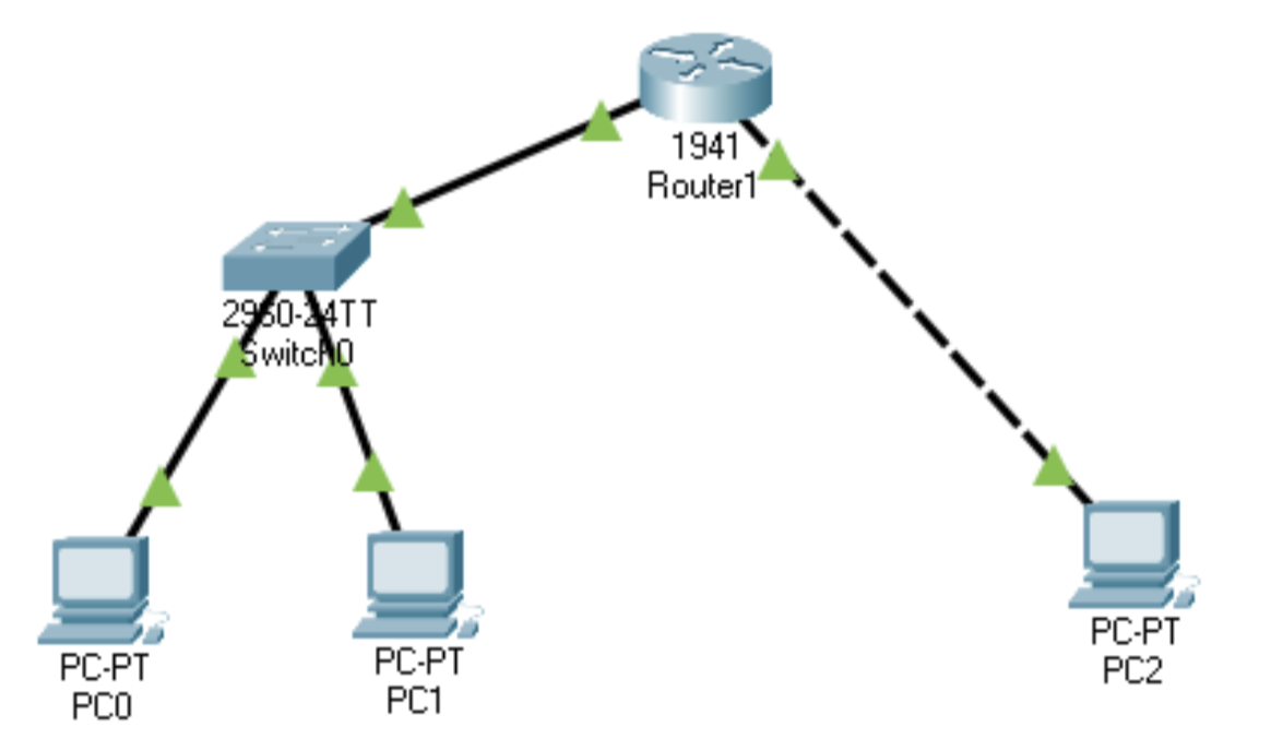
You should now have a router, a switch, and two PCs in your workspace.
4. Connect the Devices
In this step, we’ll connect the router to the switch using an Ethernet cable and connect the PCs to the switch. Follow these steps:
- On the left-hand side of the Packet Tracer window, find the “Connections” category under “Devices.”
- Select the “Copper Straight-Through” cable type. This type of cable is typically used to connect routers to switches and switches to PCs.
- Click and drag a straight-through Ethernet cable from one of the router’s Ethernet interfaces (e.g., GigabitEthernet0/0) to one of the switch’s Ethernet interfaces (e.g., FastEthernet0/1). When you hover over the router’s interface, you’ll see a green indicator, and when you hover over the switch’s interface, you’ll see a red indicator. Connect the cable by clicking on the router’s interface and then the switch’s interface.
- Next, use straight-through Ethernet cables to connect each PC to one of the switch’s Ethernet ports. Connect one end of the cable to a PC’s Ethernet port and the other end to an available port on the switch.
You have now physically connected the router to the switch and the PCs to the switch.
5. Configure the Router and PCs
Before the router can route traffic between the PCs, you need to configure it with appropriate IP addresses. Additionally, configure the PCs with IP settings so they can communicate with each other via the router. Here’s how to do it:
Configure the Router:
- Click on the router in the workspace to select it.
- At the bottom of the workspace, you’ll see a “CLI” (Command Line Interface) tab. Click on it to access the router’s command-line interface (CLI).
- In the router’s CLI, you can configure settings like the router’s hostname, interface IP addresses, and routing. For basic connectivity, you can use the following commands:
  enable
  configure terminal
  hostname Router
  interface GigabitEthernet0/0
  ip address <router_ip_address> <subnet_mask>
  no shutdown
  exit
  interface GigabitEthernet0/1
  ip address <router_ip_address> <subnet_mask>
  no shutdown
  exit
  end
  write memory
Replace <router_ip_address> and <subnet_mask> with your desired IP address and subnet mask for each interface. The “write memory” command saves your configuration.
Configure the PCs:
- Click on one of the PCs to select it.
- In the PC’s configuration panel on the right-hand side, set the following parameters:
- Name: Assign a name to the PC (e.g., PC1).
- IP Configuration: Set an IP address, subnet mask, and default gateway based on the network you’re creating. The default gateway should be the IP address of the router’s interface connected to the switch.
- Repeat the above steps for the second PC, ensuring that each PC has a unique IP address within the same subnet.
6. Test Connectivity
To verify that your network is functioning correctly, perform the following steps:
- Click on one of the PCs to select it.
- At the bottom of the workspace, you’ll see a “Desktop” tab. Click on it to access the PC’s desktop.
- Open a command prompt or terminal window, depending on the operating system emulation.
- Attempt to ping the IP address of the other PC. Use the following command (replace
<other_pc_ip>with the IP address of the other PC):
ping <other_pc_ip>If the ping is successful, it means the router is correctly routing traffic between the PCs.
7. Save Your Project
Finally, don’t forget to save your Packet Tracer project to preserve your network topology and configurations. To save your project, follow these steps:
- Click on “File” in the top menu.
- Select “Save” or “Save As” to save your project with a meaningful name and location of your choice.
Conclusion for Connecting a router to a switch in Packet Tracer
connecting a router to a switch in Packet Tracer involves several key steps, including creating a network topology, adding devices, physically connecting the devices, configuring the router and PCs, testing connectivity, and saving your project. This setup simulates a basic network scenario where a router acts as the gateway between two PCs in different network segments. Understanding this process is fundamental to building more complex network configurations and scenarios in Packet Tracer as you explore the world of networking.