Contents of this article
In this article, I describe some common steps for Configuring LAN in Packet Tracer. Local Area Networks (LANs) serve as the backbone of modern communication within organizations, homes, and educational institutions. Configuring a LAN involves a series of steps that ensure devices can communicate seamlessly within a confined network space. In this article, we will delve into the detailed process of configuring a LAN using Packet Tracer, a powerful network simulation tool commonly employed for educational and training purposes.
Understanding the Basics of LANs
Before we dive into the practical aspect of configuring a LAN in Packet Tracer, it’s crucial to understand the fundamentals of Local Area Networks. LANs are networks that connect devices within a limited geographic area, such as a single building, a floor within a building, or a campus. The primary goal of a LAN is to facilitate fast and efficient communication between connected devices, which can include computers, printers, servers, and other networking devices.
Packet Tracer: An Overview
Packet Tracer is a simulation tool developed by Cisco that allows users to design, build, and configure network topologies in a virtual environment. It is widely used in networking courses and certifications to provide hands-on experience without the need for physical hardware. Packet Tracer supports various networking devices, including routers, switches, and end devices like computers.
Creating a New Packet Tracer Project
- Launch Packet Tracer:
- Open the Packet Tracer application on your computer.
- Create a New Project:
- Click on “File” and then select “New” to start a new Packet Tracer project.
Designing the LAN Topology
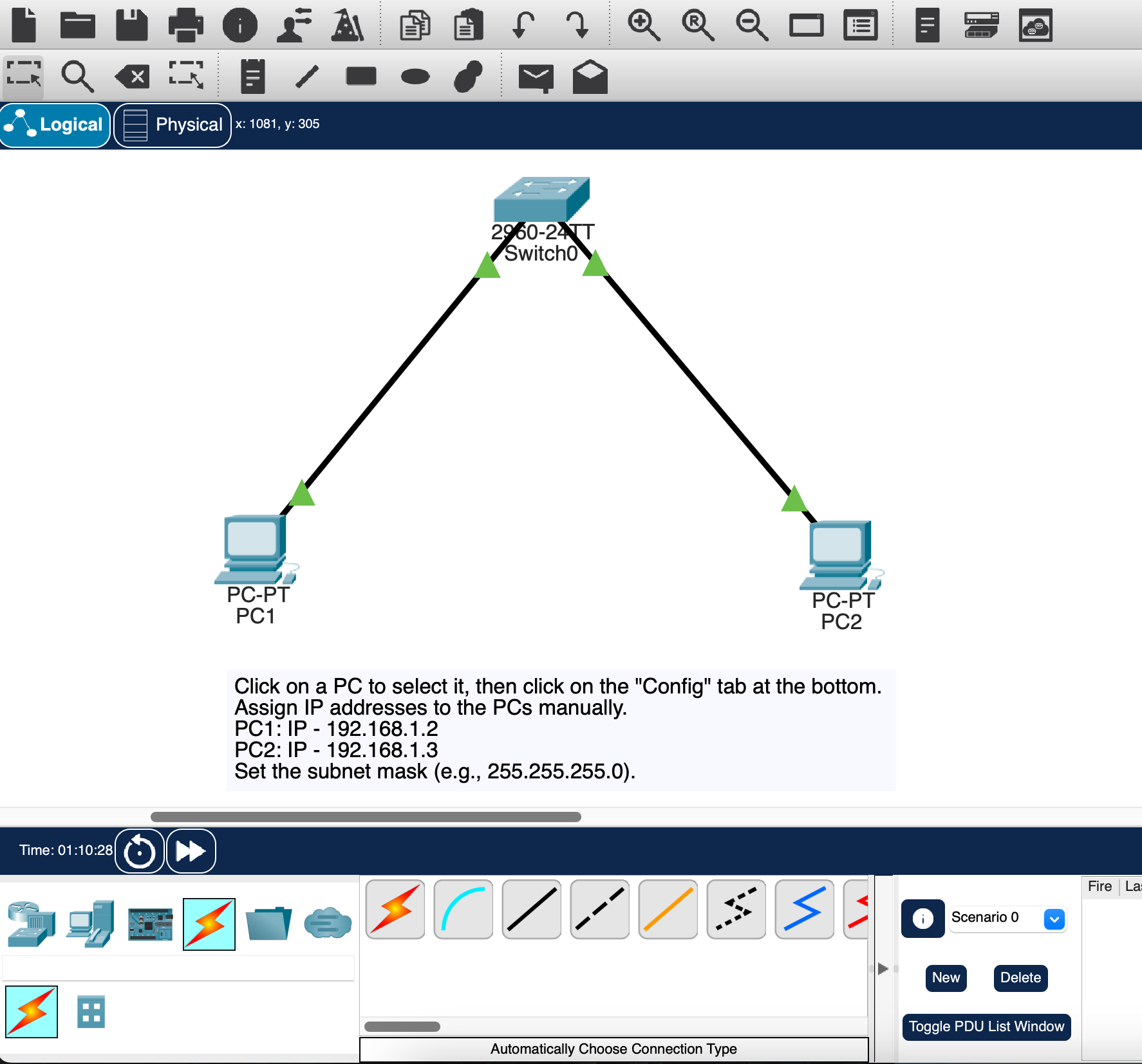
In this example, we’ll configure a simple LAN consisting of two computers connected to a switch. Follow these steps to design the topology:
- Add Devices:
- From the left panel, drag and drop devices onto the workspace. For our basic LAN, use PCs as end devices and a switch to connect them.
- Connect Devices:
- Use copper straight-through cables to connect the PCs to the switch. Click on the “Connections” button on the left panel, select the copper straight-through cable, and connect the devices by clicking on the desired interfaces on the switch and PCs.
- Arrange Devices:
- Organize the devices on the workspace for a clear and logical layout. This step is optional but can enhance the visual representation of your network.
Configuring IP Addresses on PCs
For devices in a LAN to communicate, each device must have a unique IP address within the same subnet. Follow these steps to configure IP addresses on the PCs:
- Select a PC:
- Click on one of the PCs to select it.
- Access Configuration Tab:
- Click on the “Config” tab at the bottom of the screen to access the configuration options for the selected PC.
- Assign IP Address:
- Manually assign an IP address to the PC. For example:
- PC1: IP – 192.168.1.2
- PC2: IP – 192.168.1.3
- Set the subnet mask, such as 255.255.255.0.
- Repeat for Other PCs:
- Repeat the process for the other PCs, ensuring that each PC has a unique IP address within the same subnet.
Configuring the Switch
A switch is a crucial component in a LAN, responsible for forwarding data frames between connected devices. Follow these steps to configure the switch in Packet Tracer:
- Select the Switch:
- Click on the switch to select it.
- Access Command Line Interface (CLI):
- Click on the “CLI” tab at the bottom of the screen to access the Command Line Interface (CLI) of the switch.
- Enter Configuration Mode:
Enter the following commands to configure the switch:
enable
configure terminal
interface range fa0/1 - 2    # Configuring all FastEthernet interfaces
switchport mode access      # Setting interfaces as access ports
switchport access vlan 10   # Assigning VLAN 10 to the interfaces
exit
vlan 10
name LAN_VLAN               # Naming the VLAN as LAN_VLAN
exit
write memory                # Saving the configuration
This configuration sets up VLAN 10 on the switch and assigns the connected interfaces to this VLAN.
Testing Connectivity
Once the configuration is complete, it’s essential to test connectivity to ensure that devices within the LAN can communicate effectively. Follow these steps to test connectivity:
- Open Command Prompt:
- Open the command prompt on one of the PCs.
- Ping Another PC:
- Use the “ping” command to test connectivity to another PC. For example:
ping 192.168.1.3This command sends a series of packets to the specified IP address and checks for a response, verifying that the devices can communicate within the LAN.
Optional: Configuring Additional Features
Depending on the specific requirements of your LAN, you may want to configure additional features, such as:
- DHCP Server: To automatically assign IP addresses to devices in the LAN.
- File Sharing: To enable sharing of files and resources between PCs.
- Security Measures: Implement security measures such as access control lists (ACLs) to control traffic.
Saving the Packet Tracer Project
After completing the configuration and testing, it’s crucial to save your Packet Tracer project to preserve your work. Follow these steps to save your project:
- Save the Project:
- Click on “File” and then select “Save” to save your Packet Tracer project.
Another example for Configuring LAN in Packet Tracer
1. Launch Packet Tracer:
Open Packet Tracer on your computer.
2. Create a New Network:
- Click on “File” and then select “New” to create a new network project.
3. Add Devices:
- From the left panel, drag and drop devices like computers (end devices) and a switch onto the workspace. You can use PCs as your devices and a switch to connect them.
4. Connect Devices to the Switch:
- Use copper straight-through cables to connect the PCs to the switch. Click on the “Connections” button on the left panel, select the copper straight-through cable, and connect the devices by clicking on the desired interfaces on the switch and PCs.
5. Assign IP Addresses:
- Click on a PC to select it, then click on the “Config” tab at the bottom. Assign IP addresses to the PCs manually. Make sure each PC has a unique IP address within the same subnet. For example:
- PC1: IP – 192.168.1.2
- PC2: IP – 192.168.1.3
- Set the subnet mask (e.g., 255.255.255.0).
6. Configure Switch:
Click on the switch to select it, then click on the “CLI” tab at the bottom to access the Command Line Interface.
Enter the following commands to configure the switch:
enable
configure terminal
interface range fa0/1 - 2    # Configuring all FastEthernet interfaces
switchport mode access      # Setting interfaces as access ports
switchport access vlan 10   # Assigning VLAN 10 to the interfaces
exit
vlan 10
name LAN_VLAN               # Naming the VLAN as LAN_VLAN
exit
write memory                # Saving the configuration
This configuration sets up VLAN 10 on the switch and assigns the connected interfaces to this VLAN.
7. Test Connectivity:
- Open a command prompt on one PC and use the “ping” command to test connectivity to another PC. For example:
bash ping 192.168.1.3
8. Save Your Project:
- Click on “File” and then “Save” to save your Packet Tracer project.
This basic LAN configuration creates a simple network with two PCs connected to a switch. The switch is configured to operate in VLAN 10, and the PCs have manually assigned IP addresses within the same subnet. Testing connectivity ensures that devices within the LAN can communicate with each other.
Keep in mind that this is a basic setup, and in larger LANs, more advanced configurations, such as implementing routers, DHCP servers, and additional switches, may be necessary. The specific requirements will depend on the intended use and complexity of the LAN.
Conclusion for Configuring LAN in Packet Tracer
Configuring LAN in Packet Tracer is a valuable hands-on exercise that allows individuals to apply theoretical knowledge in a practical setting. Through the detailed steps outlined in this article, users can create a basic LAN topology, assign IP addresses, configure a switch, and test connectivity. Understanding the fundamentals of LAN configuration is essential for anyone entering the field of networking, and tools like Packet Tracer provide a safe and immersive environment for learning.
As technology continues to advance, the demand for skilled network professionals remains high. Whether pursuing a career in network administration, cybersecurity, or system engineering, the ability to configure and manage LANs is a fundamental skill. Packet Tracer serves as an excellent platform for honing these skills, offering a simulated environment where users can experiment with various network configurations and scenarios.
In conclusion, the process of configuring LAN in Packet Tracer provides a solid foundation for understanding networking principles and prepares individuals for real-world scenarios. Aspiring network professionals are encouraged to explore and experiment with different network topologies, devices, and configurations to broaden their knowledge and expertise in the dynamic field of networking.
Configuring LAN in Packet Tracer involves setting up the devices, connecting them, and assigning appropriate configurations to enable communication within the network. Below is a step-by-step guide to configure a simple LAN using Packet Tracer. I hope you found this article helpful. You may comment below or contact us for any query related to the contents of this website.