Contents of this article
In this article I explain the configuration of OSPF in Multi Area. Here Multi Area means the routers belongs to different area. Before going to configuration of OSPF in Multi Area let’s revise some common features of OSPF. OSPF is a link state routing protocol. OSPF works at layer 3 of OSI which is known as network layer.
Routing devices works on network layer like router. OSPF uses port number 89 for routing. The Administrative Distance AD is by default 110. OSPF use 224.0.0.5 IP address for multicast and 224.0.0.6 for updates. There are some predefined terms which make OSPF working. OSPF supports both IPv4 and IPv6. These terms are known as OSPF fundamental terminology. It is necessary to understand these terms for CCNA exam.
Wildcard mask for configuration of OSPF in single area
In a LAN the subnet mask defines the network for communication. Suppose I have a network with network ID 192.168.1.0/24. All devices lies in the network 192.168.1.0/24 can communicate with each other. But what if I want to deny only single network and allow all other networks. For example I want to allow all network ID packets in my network except 192.168.1.0/24. In this case I use the wildcard mask to deny all traffic from the network 192.168.1.0/24.
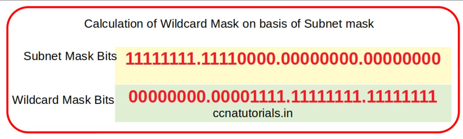
So wildcard mask is inverted value of subnet mask. Just replace the 1 by 0 and 0 by 1 in subnet mask the result will be wildcard mask. For example for network ID 192.168.1.0/24 the subnet mask is 255.255.255.0 and wildcard mask is 0.0.0.255. Similarly, for subnet mask 255.255.255.252 the wildcard mask will be 0.0.0.3. Wildcard mask used in configuration of OSPF in single area.
Topology of network required the configuration of OSPF in Multi area.
To explain the configuration of OSPF in Multi area I select the network topology as shown in below diagram. There I take three routers connected with each other. A PC is connected with each router. The IP address schema is shown in the image below. Router R1 lies at the border of three different area. So each interface or router lies in different area and assigned IP address accordingly. The Process ID of all routers is same 1.
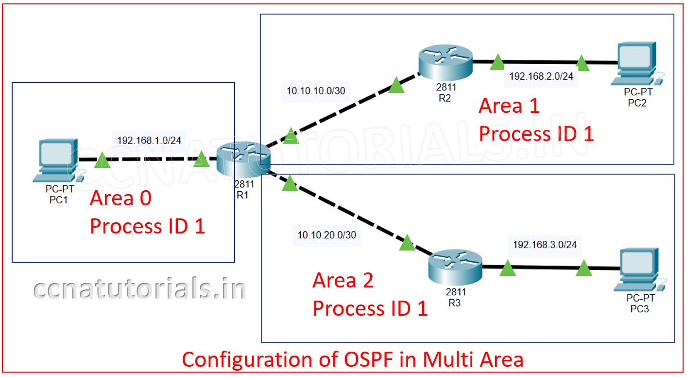
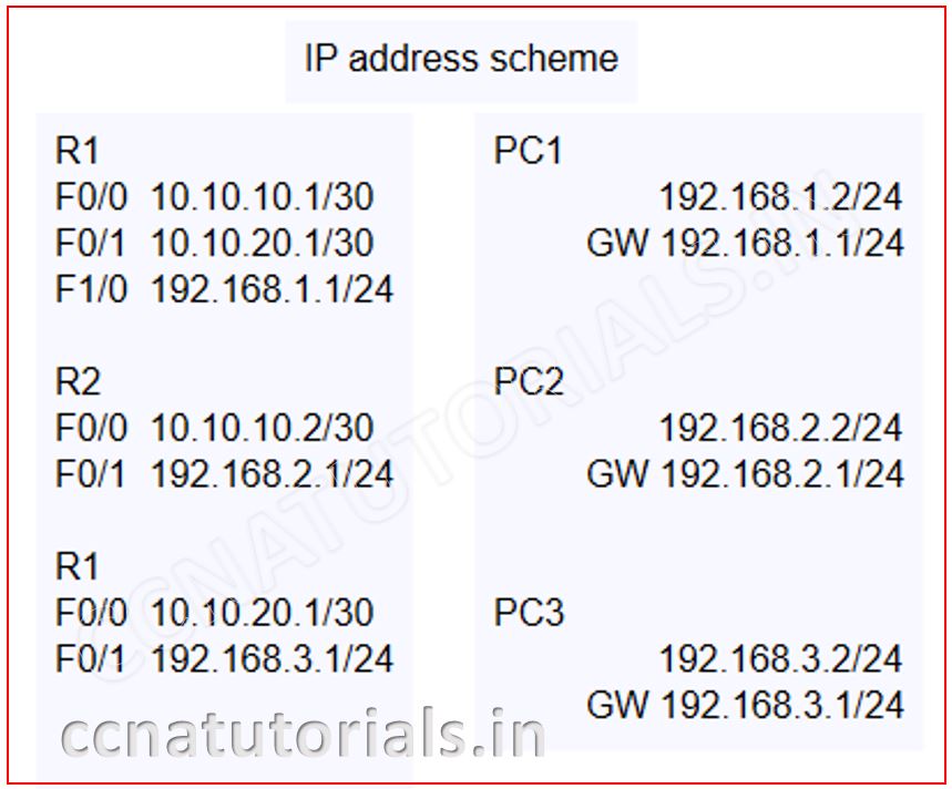
After completion of connectivity we need to assign the IP address to each PC. The IP address and gateway of each PC is set according to the image. After assigning the IP address in PCs we need to configure the routers.
Firstly assign the IP address to different interfaces of the router. To do so run the below commands in CLI of router R1.
 Router>en
 Router#config t
 Router(config)#hostname R1
 R1#config t
 R1(config)#interface fastEthernet 0/0
 R1(config-if)#ip address 10.10.10.1 255.255.255.252
 R1(config-if)#no shut
 R1(config-if)#exit
 R1(config)#interface fastEthernet 0/1
 R1(config-if)#ip address 10.10.20.1 255.255.255.252
 R1(config-if)#no shut
 R1(config-if)#exit
 R1(config)#interface fastEthernet 1/0
 R1(config-if)#ip address 192.168.1.1 255.255.255.0
 R1(config-if)#no shut
 R1(config-if)#exit
 R1(config)#do wr
 Building configuration...
 [OK]
 R1(config)#
Similarly run the below commands in router R2 to assign the IP address on interfaces of Router R2.
 Router>en
 Router#config t
 Router(config)#hostname R2
 R2(config)#interface fastEthernet 0/0
 R2(config-if)#ip address 10.10.10.2 255.255.255.252
 R2(config-if)#no shut
 R2(config-if)#exit
 R2(config)#interface fastEthernet 0/1
 R2(config-if)#ip address 192.168.2.1 255.255.255.0
 R2(config-if)#no shut
 R2(config-if)#exit
 R2(config)#do wr
 Building configuration...
 [OK]
 R2(config)#exit
 R2#
Now run the following commands in Router R3 to assign the IP address to each interface.
 Router>en
 Router#config t
 Router(config)#hostname R3
 R3(config)#interface fastEthernet 0/0
 R3(config-if)#ip address 10.10.20.2 255.255.255.252
 R3(config-if)#no shut
 R3(config-if)#exit
 R3(config)#interface fastEthernet 0/1
 R3(config-if)#ip address 192.168.3.1 255.255.255.0
 R3(config-if)#no shut
 R3(config-if)#exit
 R3(config)#do wr
 Building configuration...
 [OK]
 R3(config)#exit
 R3#
By running above all commands the link of each router is up. The PC can communicate with the gateway. Try to ping the PC with each other you can see the PC are not able to ping with each other. See the commands below in PC1.
 C:\>ping 192.168.2.2

 Pinging 192.168.2.2 with 32 bytes of data:

 Reply from 192.168.1.1: Destination host unreachable.
 Reply from 192.168.1.1: Destination host unreachable.
 Reply from 192.168.1.1: Destination host unreachable.
 Reply from 192.168.1.1: Destination host unreachable.

 Ping statistics for 192.168.2.2:
 Packets: Sent = 4, Received = 0, Lost = 4 (100% loss),
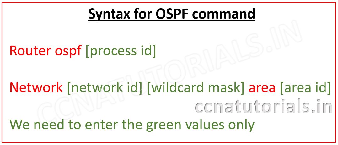
Now we require to configure the OSPF in each router to make possible the communication in the network. The syntax of OSPF commands is shown in below image.
Here the process ID 1 Area ID is 0, 1 and 2. So firstly configure the OSPF in router R1. Run the below commands in router R1.
 R1>en
 R1#config t
 R1(config)#router ospf 1
 R1(config-router)#network 192.168.1.0 0.0.0.255 area 0
 R1(config-router)#network 10.10.10.0 0.0.0.3 area 1
 R1(config-router)#network 10.10.20.0 0.0.0.3 area 2
 R1(config-router)#exit
 R1(config)#do wr
 Building configuration...
 [OK]
 R1(config)#
Now run the below commands in Router R2. The Router R2 is internal router for area 1 and process ID is 1.
 R2#
 R2#config t
 R2(config)#router ospf 1
 R2(config-router)#network 10.10.10.0 0.0.0.3 area 1
 R2(config-router)#network 192.168.2.0 0.0.0.255 area 1
 R2(config-router)#exit
 R2(config)#do wr
 Building configuration...
 [OK]
 R2(config)#
Now run the below commands in Router R3 to configure the OSPF. Process ID is 1 and area ID is 2 for router R3.
 R3#
 R3#config t
 R3(config)#router ospf 1
 R3(config-router)#network 10.10.20.0 0.0.0.3 area 2
 R3(config-router)#network 192.168.3.0 0.0.0.255 area 2
 R3(config-router)#exit
 R3(config)#do wr
 Building configuration...
 [OK]
 R3(config)#
Checking the configuration of OSPF in Router R1.
After configuration of OSPF in routers you can check the routing protocol by running the command show ip ospf command see the example below. Here the bold text show the OSPF routing protocol and the network configured with OSPF.
  R1#show ip ospf
  Routing Process "ospf 1" with ID 192.168.1.1
  Supports only single TOS(TOS0) routes
  Supports opaque LSA
  It is an area border router
  SPF schedule delay 5 secs, Hold time between two SPFs 10 secs
  Minimum LSA interval 5 secs. Minimum LSA arrival 1 secs
  Number of external LSA 0. Checksum Sum 0x000000
  Number of opaque AS LSA 0. Checksum Sum 0x000000
  Number of DCbitless external and opaque AS LSA 0
  Number of DoNotAge external and opaque AS LSA 0
  Number of areas in this router is 3. 3 normal 0 stub 0 nssa
  External flood list length 0
     Area BACKBONE(0)
         Number of interfaces in this area is 1
         Area has no authentication
         SPF algorithm executed 4 times
         Area ranges are
         Number of LSA 5. Checksum Sum 0x037f29
         Number of opaque link LSA 0. Checksum Sum 0x000000
         Number of DCbitless LSA 0
         Number of indication LSA 0
         Number of DoNotAge LSA 0
         Flood list length 0
     Area 1
         Number of interfaces in this area is 1
         Area has no authentication
         SPF algorithm executed 3 times
         Area ranges are
         Number of LSA 6. Checksum Sum 0x03b699
         Number of opaque link LSA 0. Checksum Sum 0x000000
         Number of DCbitless LSA 0
         Number of indication LSA 0
         Number of DoNotAge LSA 0
         Flood list length 0
     Area 2
         Number of interfaces in this area is 1
         Area has no authentication
         SPF algorithm executed 5 times
         Area ranges are
         Number of LSA 6. Checksum Sum 0x04111c
         Number of opaque link LSA 0. Checksum Sum 0x000000
         Number of DCbitless LSA 0
         Number of indication LSA 0
         Number of DoNotAge LSA 0
         Flood list length 0


 R1#
Similarly, you can check the OSPF configuration in all routers. Now you can also ping all PCs with each other. See the example of Ping in below command.
 C:\>ping 192.168.2.2

 Pinging 192.168.2.2 with 32 bytes of data:

 Reply from 192.168.2.2: bytes=32 time=1ms TTL=126
 Reply from 192.168.2.2: bytes=32 time<1ms TTL=126
 Reply from 192.168.2.2: bytes=32 time<1ms TTL=126
 Reply from 192.168.2.2: bytes=32 time<1ms TTL=126

 Ping statistics for 192.168.2.2:
 Packets: Sent = 4, Received = 4, Lost = 0 (0% loss),
 Approximate round trip times in milli-seconds:
 Minimum = 0ms, Maximum = 1ms, Average = 0ms

 C:\>ping 192.168.3.2

 Pinging 192.168.3.2 with 32 bytes of data:

 Reply from 192.168.3.2: bytes=32 time=1ms TTL=126
 Reply from 192.168.3.2: bytes=32 time<1ms TTL=126
 Reply from 192.168.3.2: bytes=32 time<1ms TTL=126
 Reply from 192.168.3.2: bytes=32 time<1ms TTL=126

 Ping statistics for 192.168.3.2:
 Packets: Sent = 4, Received = 4, Lost = 0 (0% loss),
 Approximate round trip times in milli-seconds:
 Minimum = 0ms, Maximum = 1ms, Average = 0ms
 C:\>
So this is all about the configuration of OSPF in multi area. I hope you found this article helpful with practical hand. For any query or suggestion drop a comment below or contact us. Your suggestions are always welcome by us.