In this article I describe the commands to Configure NTP in Router for CCNA exam. We need to Configure NTP in Router when the time synchronisation is required in the network. NTP stands for Network Time Protocol. Generally a standard NTP server is required in the network for synchronisation of time in the networking devices. We can also use a router as a NTP server for all the networking devices. So in this article i provide some content related to Configure NTP in Router.
We know the running and startup configuration of router. When we initial Configure NTP in Router the configuration saved in the running configuration file. We need to save the backup of current running configuration to the startup configuration file. By doing this we will not lost our work in case of power failure of the router. Let’s remember the memories used in the router before learning the Configure NTP in Router.
NTP synchronise the clock of all network devices in the network. Time synchronisation is necessary for all network devices, servers and computers in a LAN. It is very difficult to maintain the time synchronisation manually for all networking devices and machines. Many applications run on time if the time is not synchronise these application may give errors. Cisco router have a feature to configure NTP with NTP server.
RAM
RAM is an acronym that stands for Random Access Memory. RAM of a router works like RAM of a computer. RAM is a volatile memory so it needs power all time. Router loads the IOS and the configuration file in RAM when the router is power on or reboot. It store the data like routing table and running config files. Data transfer speed of RAM of router is very fast. The running configuration remain save in the RAM or router until the power is available. Later these settings can be copied to start up configuration for future use. RAM stores data in power on condition of router. All data in RAM erased automatically if router is power off. The size of RAM in router is generally in MB. The size may be 16 MB, 32 MB.
RAM of a router keep the running configuration file, routing table and other information related to the interfaces of the router. When we works on CLI of a router actually we are working in the RAM of router. To take the back up configuration of Router, We need to copy the running configuration into startup configuration to save the current settings of the router. The startup configuration saved in the NVRAM which can be used later after rebooting the router.
ROM
ROM is acronym that stands for Read Only Memory. Data on ROM is write once only. After writing the data on ROM router can read the data but can not change it. ROM stores the bootstrap of IOS which is responsible to boot the router. Bootstrap find the IOS image file and run the IOS in RAM of router. ROM keep the instructions for POST process when router is power ON. ROM is chip on motherboard and it is programmed once only. ROM is just like the BIOS system of the computer. The booting process starts from the ROM of the router. ROM is a non volatile memory which does not require any power all the time to keep save the information in it. We can not do any changes in the ROM of a router. The settings of ROM configured by the firm so it is generally known as a firmware. The another internal component of router is NVRAM which is very similar to the ROM.
NVRAM
NVRAM keep the startup configuration file which is a backup copy of the running configuration. For back up configuration of Router we need to copy the running configuration to the startup configuration. Every time when the router power on the settings of startup configuration loaded into the RAM of the router. NVRAM is also a non volatile memory similar to ROM. In switches NVRAM stores the information of VLANs. When we configure VLAN in a switch the VLAN configuration saved into the NVRAM memory of the switch. NVRAM stands for Nonvolatile Random Access Memory.
NVRAM is like RAM but it is non volatile memory. It means NVRAM stores the data after power of the router. NVRAM stores the startup config file. Startup config file contains the routing table and other configuration which was copied from a running config file. The difference between NVRAM and ROM is that the content of ROM can not be changed but the content of NVRAM is changeable. When router is power on it search the startup config file in NVRAM only.
Flash Memory
Flash memory is a kind of EEPROM. EEPROM stands for Electrically Erasable Programmable Read-Only Memory. The content of Flash memory can not be change like ROM. Flash memory stores the IOS image. The data of Flash memory remain unchanged when the router is reboot or power off. We can say the operating system of router IOS saved in the flash memory. Every time when a router is power on the IOS loaded into the RAM from the Flash memory. The IOS checks all the interface of router when loaded first time in the RAM. To know all the functions or internal component of router you can read the full article related to booting sequence here.
Configure NTP in Router explained
Time synchronisation is necessary for routers and switches for maintaining the syslog. We know that router and switches generates event log during all different events. If the time is not synchronised the event generation can be interrupted. To avoid these interruption we have to configure a separate NTP server within the network. These syslog contain a timestamp as we discuss in previous article. The timestamp service can be manually configured to be enable or disable. To keep the timestamp service enable we can run the below command
 Router>en
 Router#config t
 Enter configuration commands, one per line.  End with CNTL/Z.
 Router(config)#hostname ccnatutorials
 ccnatutorials(config)#service timestamps log datetime msec
 ccnatutorials(config)#
by running above command all the syslogs of router will keep a timestamp. You can see the time is in miliseconds. So it is very difficult to synchronize the time in miliseconds manually. So we have to configure a NTP server in the network.
How to configure NTP in router
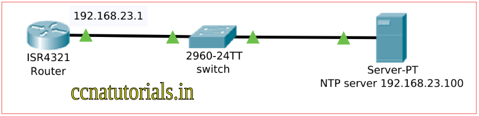
To configure a NTP server we taken the scenario shown in the image below.
Before configure NTP in router you can check the NTP status by running following command in router. You can see the clock in unsynchronized in the status. You need to configure NTP in router with a NTP server.
 ccnatutorials#show ntp status
 Clock is unsynchronized, stratum 16, no reference clock
 nominal freq is 250.0000 Hz, actual freq is 249.9990 Hz, precision is 2**24
 reference time is 00000000.00000000 (00:00:00.000 UTC Mon Jan 1 1990)
 clock offset is 0.00 msec, root delay is 0.00  msec
 root dispersion is 0.00 msec, peer dispersion is 0.00 msec.
 loopfilter state is 'FSET' (Drift set from file), drift is - 0.000001193 s/s system poll interval is 4, never updated.
 ccnatutorials#
Now we required to configure NTP in router. We have to run the following commands in router to synchronise with a NTP server.
 ccnatutorials(config)#ntp server 192.168.23.100 ?
   key  Configure peer authentication key
   <cr>
 ccnatutorials(config)#ntp server 192.168.23.100
 ccnatutorials(config)#
Here key is used for authentication for NTP server. You can run the command without using key but the authentication system in server should be disabled. You need to run the above command in all your network devices like switches and routers. Once you run the command in all network devices the time will synchronise in them. After synchronisation of time you can enable the timestamp service for event logs of router. To check the NTP service status we need to run the following command in router.
 ccnatutorials#show ntp status
 Clock is synchronized, stratum 8, reference is 127.127.1.1
 nominal freq is 250.0000 Hz, actual freq is 249.9990 Hz, precision is 2**24
 reference time is FFFFFFFFAF1EE1E8.000003A9 (1:18:32.937 UTC Mon Mar 1 1993)
 clock offset is 0.00 msec, root delay is 0.00  msec
 root dispersion is 0.00 msec, peer dispersion is 0.12 msec.
 loopfilter state is 'CTRL' (Normal Controlled Loop), drift is - 0.000001193 s/s system poll interval is 5, last update was 8 sec ago.
 ccnatutorials#show clo
 ccnatutorials#show clock
 1:19:55.680 UTC Mon Mar 1 1993
 ccnatutorials#
We see in the above example the Clock is synchronized with the server. Similarly you can synchronize all devices with this server. But you need to configure the server as a NTP server. You can set the key and password for authentication.
In this article I describe the process of configure ntp in router. I hope you found this article helpful. For any query or suggestion on this article you may contact us or drop a comment below. Your suggestions are always welcome by us.